Jennings Organ Company - Model A organ
In progress, August 2022
Thanks to David, a series of pictures of one of the first Jennings Model A organs produced, serial number A2, probably first half of 1956, designed for use in churches and chapels. It was bought new by a gentleman in Corby, Northants and later went to Weldon Congregational Church. Further details and info to follow.
For early advertising material issued by the Jennings Organ Company, see this page. The Model A required a separate speaker unit ("tone cabinet").

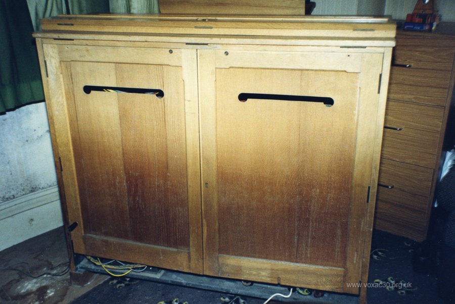
General front view.
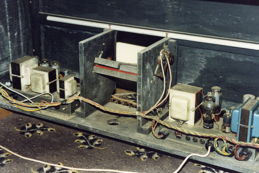
The rear: lowest level at left, the power amplifier (sound), with two EL34s; at right the voltage supply amplifier - termed the "Power Pack" by JMI - providing the HT voltage and 6.3v lines for the valve heaters. In the centre, the 8 ranks of generators for the 8 octaves of the keyboard. The generators each have six ECC83 (12AX7) valves - Mullards and Brimars - to produce the twelve notes of the octave, one half of an ECC83 per note (ECC83s embody two completely separate triodes in a single glass envelope). At top, the rear of the tone/stops assembly.
The white bar above the opening for the volume pedals is a heater - a "damp chaser". The note generators of valve organs are particularly prone to changes of temperature, quickly falling out of tune. Details of a generator array to come.

A closer shot of the power sections: on the left, the audio amplifier (30 watt) with its two EL34s; on the right the HT voltage and valve heater supply unit. Transformers were supplied by Haddon to Derek Underdown's specifications. Valves are a mixture of Brimar and Mullard. Audio output was driven to one or more external "tone cabinets", Jennings's name for speaker cabs. These came in a variety of sizes (the largest ones often as large as the organ itself) and contained arrays of speakers as required - from 18" bass drivers to Goodmans Midax and Trebax horns and anything in between.
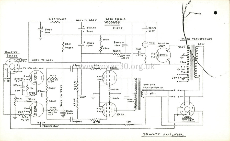
Derek's 30 watt amplifier design, later taken up in the Vox AC2/30. In mid 1963, its bias circuit was reworked for the Vox AC50 mark 1.
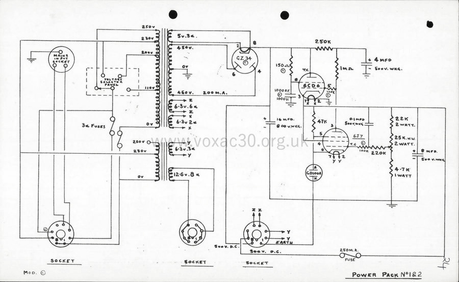
The Power Pack circuit, as above, from the "Jennings Organ Company" service manual.
Work done by Derek in the 1950s paid dividends also in the 1960s. His experience was instrumental in the equipping and production of numerous Vox amplifiers and speaker cabs. Goodmans Midax horns, for instance, did not suddenly come into the picture in early 1964 as has sometimes been said. Derek knew them and had employed them years earlier.
Preliminary to the pictures (further below) of one of the generator arrays in the organ, a couple of sheets from an early "Jennings Organ Company" service manual. These were fairly lengthy loose-leaf books containing sets of pages on tuning, troubleshooting, as well as circuit diagrams for the various models.
Below, a copy of OOS/001 - Oscillator no. 1 - which corresponds with the circuits in the Model A, and the Oscillator no. 2 sheet for the "V-series" organs (of which the Model A was a member).
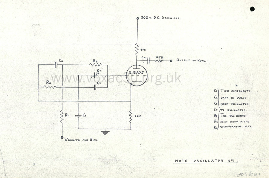
Jennings Organ Company, sheet OOS/001. The text at right reads: "These components (C1, C2, C3, C4, R1, R2, R3) vary in value from oscillator to oscillator. The full range being shown in the accompanying lists."
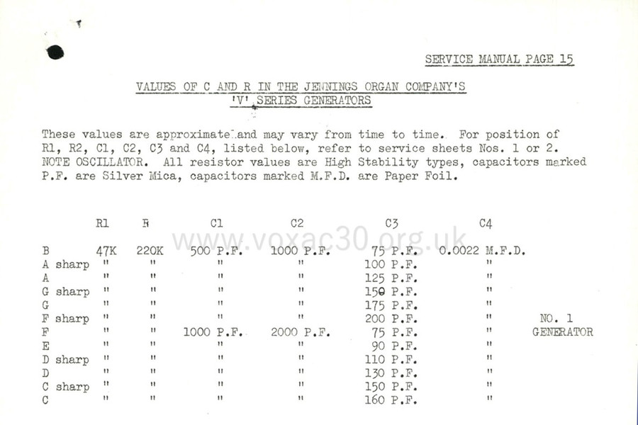
Jennings Organ Company, service manual, capacitor and resistor arrays for the V-series organ generators.
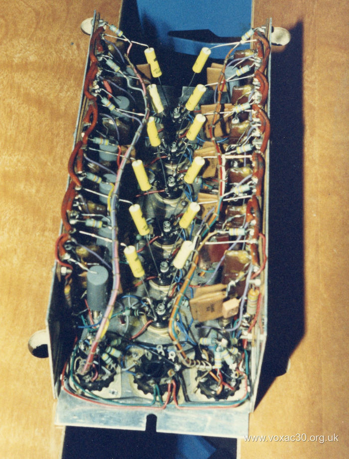
Below, shots of an assembly. On top, the six ECC83s for the generation of the 12 notes of the octave, and on insulated bases, the variable mica capacitors for tuning ("tuning control trimmers"). On the underside, the capacitor and resistor arrays.
A fairly detailed guide to tuning Jennings organs was provided in the Service Manual by Derek Underdown, the introductory paragraphs of which are below.

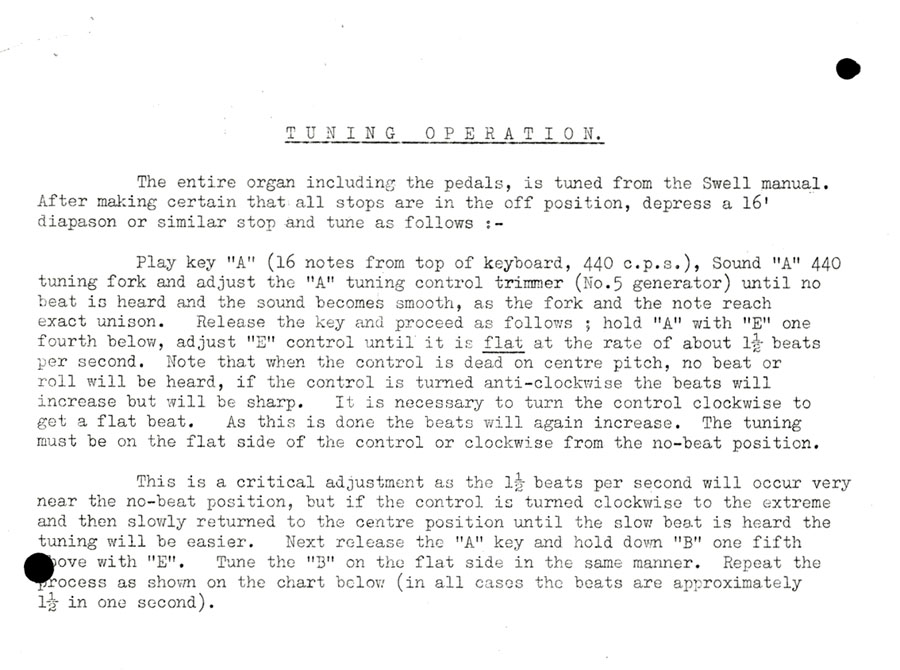
A detail from the "Jennings Organ Company" Organ Service Manual, late 1950s.
A detail of the two expression pedals and the locating connectors of the 30-note pedal board of the Model A. Underneath, the "Jennings Organ Company" schema for the pedal contact assemblies.

