An experimental chassis, Vox AC10 / Vox AC15, 1965
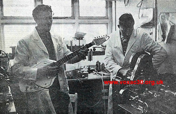
Upper floor of 119 Dartford Road, the Research and Development Room: Dick Denney with the Guitar Organ, Bob Larkin at right. Local Kent press, December 1964.
On this page, some shots of and notes on a chassis owned by the late Alan Vale, thought - perhaps not wrongly - to have been made (in whole or part) by Dick Denney.
On the back panel in felt tip: "DICK DENNY (sic) PROTOTYPE JMI VOX / £500+ ALL ORIGINAL LESS VALVES". It may be that the person who wrote the note did not know Denney in person. From what one can see, the chassis should really be termed experimental rather than a "prototype" however.
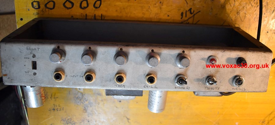
Format: designed to hang from the top of a cab (along the lines of Fender chassis). All controls are forward facing, sockets and fittings too, including an extension speaker socket. Perhaps at this point in the experimentation the cabinet was envisaged as being substantially deeper than the chassis as we have it.
The circuitry: stands in close relation to the Thomas Organ Vox Pacemaker (V-2) on the one hand, and to JMI's UL710 (without reverb) on the other. The output transformer is a Parmeko, possibly also the mains. There is no choke. The valves will have been: EZ81 rectifier, two EL84s, and two ECC83s.
Controls (left to right) are: Volume; Treble; Bass; and Tremolo Speed and Depth. At left, a bright switch, and below the controls: two inputs; a footswitch socket; an extension loudspeaker socket; and three switches - Standby, Polarity, Mains.
A fuller account of the circuit to follow.
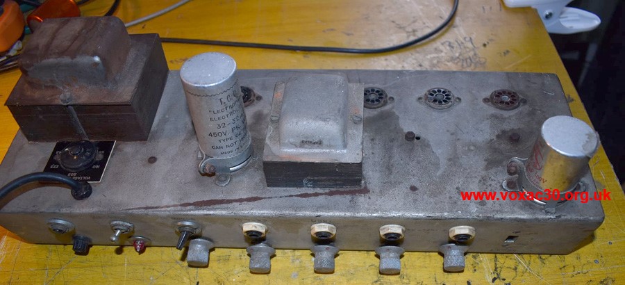
Dome voltage selector.
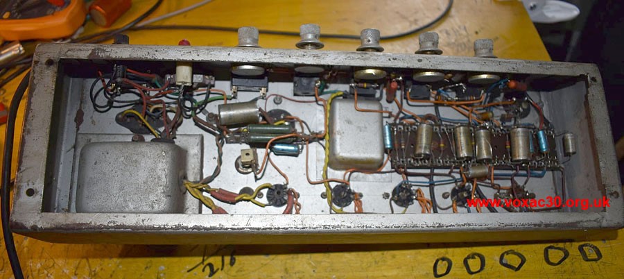
Unusually orange wire was used for the heater runs (and elsewhere in the circuit). Heater wiring was normally brown and black in JMI amps.
Evidently this chassis sprang from JMI's drive during the course of late 1964 and 1965 to produce further models for the American market, ratified by the Underwriters Laboratory (UL).
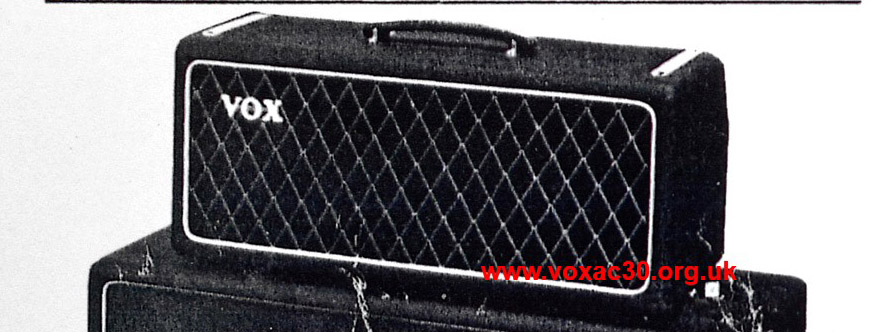
Below, a detail from a large flyer produced for the Trade Show at the Russell Hotel in August '65. On the face of things, the set illustrated looks like an AC50, but the chassis is clearly suspended from the top of the amplifier section cabinet, and there is a sloping section at back for the controls.
The format of the chassis will in other words have been the same as Alan's: three blank sides, all controls and sockets on a single sloping fascia, rearward rather than forward facing.
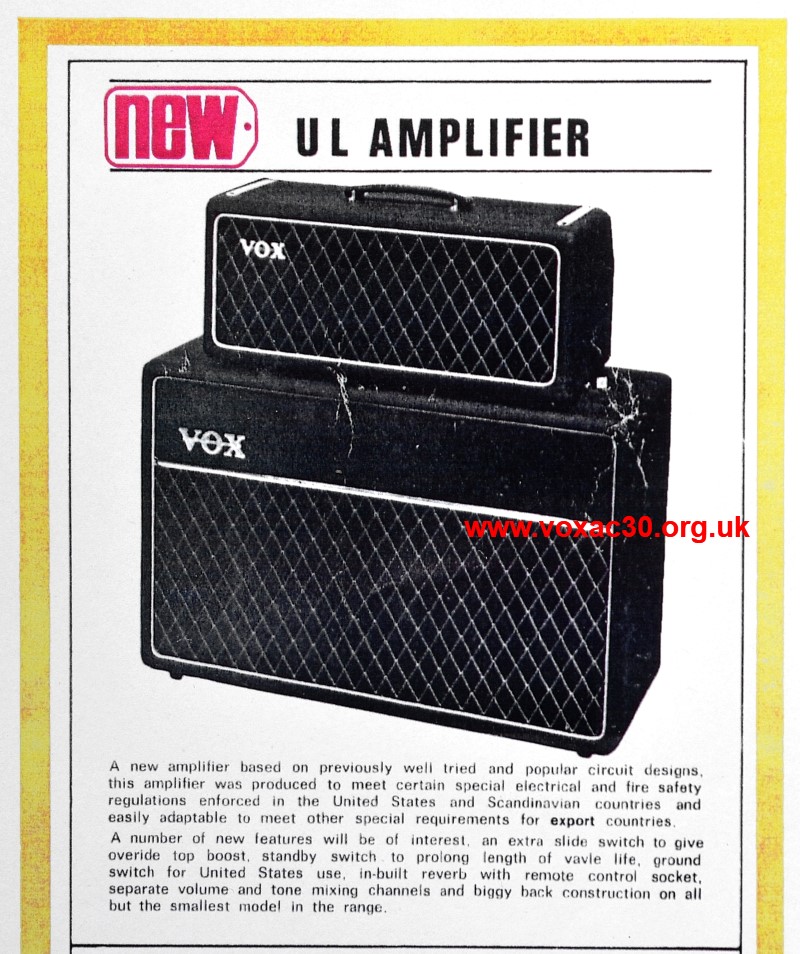
Detail from one of the two versions of the flyer produced for the Trade Show of August '65. Both had the same illustrations but slightly different texts and graphics. Note the mention of a slider switch for Top Boost (bright switch), and ground ("Polarity") switch.
Straps on top of the cabinet (much as Fenders) for the chassis securing bolts, sloping fascia at rear with the controls, the rear of the chassis inaccessible inside the cabinet.
It is not known whether the chassis below was intended for a 10-15W Twin or Super Twin ("piggy-back") in the new range envisaged by JMI.
For earlier AC10s see the index page here.