Vox AC30s assembled in Italy - the Top Boost circuit
1968 to 1972: serial numbers in the 2000s, 5000s, 6000s, 30000s
Serial numbers in the 2000s and 5000s are AC30 Top Boosts, 1968-1970; those in the 6000s and 30000s are Top Boost Reverbs, 1970-1972. For further details and general orientation, see this page.
Thanks to Lou, some new material on the Top Boost circuit. On the E.M.E. circuit diagram for the AC30, drawn out in late 1968, the cathode bypass capacitor (25uf) of the ECC83 that drives the top boost network has a dotted line around it.
An "A" in a circle indicates the presence of a note, which is to be found above the information panel: "Solo sullo schema elettrico originale" - "only on the original circuit diagram". The diagram as a whole can be seen towards the end of this page.
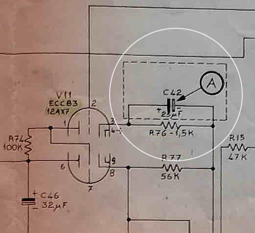

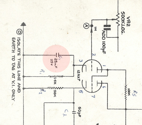
Details from the E.M.E circuit diagram for Italian-made AC30s.
As Lou notes, Italian-made AC30s - Top Boost and Top Boost Reverbs - conventionally do not have this capacitor. The page on these amps, which will need updating, can be found here.

Italian-made AC30 serial number 30748.
JMI
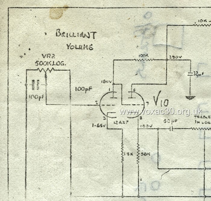
The position of the 25uf bypass cap in amplifiers assembled for JMI by Westrex and Burndept can be seen in the details below:
Detail from the JMI diagram for the Top Boost circuit. A page illustrating the various versions can be found here.
A chassis with with integral top boost in its copper control panel, assembled by Westrex, serial number of the AC30 unknown, but likely to have been in the 10000s.

Detail of the chassis of AC30 Super Twin serial number 5438 TB, assembled by JMI/Burndept - probably early 1967. Its Woden choke has the date code "KX" = October 1966.
Whether the text of the note on the Italian sheet means that the sheet as a whole was a close copy of some pre-existing (consolidated) JMI diagram for amps with integrated Top Boost is difficult to say for certain. No JMI sheet for these amps has come to light. But there must have been one (as has been mentioned previously).
It is interesting to find though that OS/013, drawn up by "Vox Sound Equipment Limited" in late 1969 shortly before it collapsed, makes just the same omission as the E.M.E. diagram - no 25uf bypass capacitor for the top boost driver valve. This capacitor certainly seems to have been omitted from the English-made AC30 chassis assembled by VSEL and VSL with traditional tag boards (1969-1971); and probably also from the Birch-Stolec PCB-based amps of 1971-1973.
Detail from OS/013, dated 20th November, 1969. Could the capacitor have been erased? There would otherwise be no reason to represent the 1.5K resistor with such a dog leg line.
The circuit diagram for Italian-made AC30s

The information panel.

The sheet as a whole.
Above, the circuit diagram for the AC30 drawn up in Italy by E.M.E - thanks to Michael. The date of the drawing is given as "17/11/68", On 28th Feb. 1972, the sheet was stamped and signed off. The circuit encompassed is the AC30 Top Boost.