Vox AC/30 serial number 4158
Late 1960

Some dimensions
Notes on the main external dimensions of the TV Front AC30. These are given in inches and fractions of inches:
CABINET
Main body of case: 21 1/2" tall x 21 3/4" wide x 10 3/8" deep.
Sides, top, and bottom: 5/16" thick.
Front surround: 3/8" thick; sides and bottom at front: 1 3/4" wide; top at front: 2 1/2 wide.
Control panel cut-out: 16 1/2" x 2 5/8", 1 1/2" from back edge of case.
Handle (dimensions taken from rear of case): centres of mounting hole pairs: 1 3/4" apart, 5" from rear edge of amp; leftmost hole is 6 5/8" from side; right-most hole is 8 3/16" from other side.
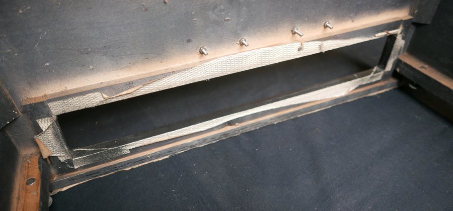
Underside of the top of the cabinet showing the battens beneath the control panel cut-out and the off-set fixings of the handle.
BAFFLE
Main dimensions: 18 1/4" tall x 18 3/4" wide x 3/4" thick.
Speaker cut-out: 10 5/16" diameter, 1 1/4" from bottom of baffle.
Vent: 12 7/8" long x 5/16" tall, centred, 3 1/2" from top of baffle.
BACK BOARD
Main dimensions: 19 5/8" tall x 19 3/4" wide x 1/8" thick.
Support for the back panel.
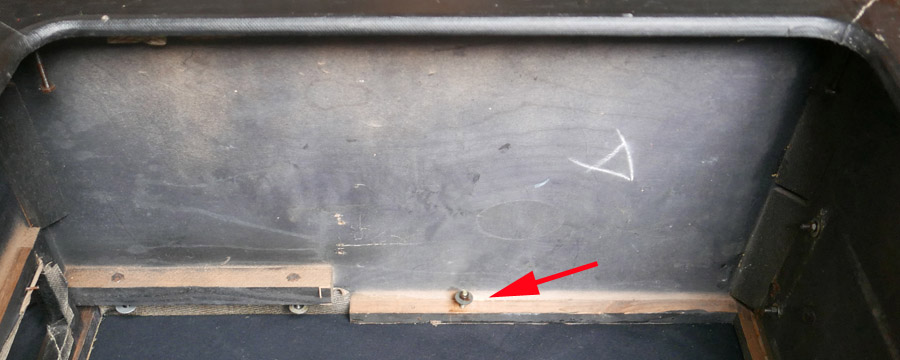
In company with most other AC/15s and AC/30s, serial number 4158's relatively flimsy pressed cardboard back board was attached to the main body of the cabinet by screws at its sides. It is clear from the surviving hardware, however, that 4158's cabinet also had a removable batten to provide further support. The screw hole that aligned with the batten is indicated in the picture below.
The batten slotted over two screws inset in the runners on the left and right hand side of the cabinet. Precisely what form it took is unknown - probably a straight piece of 1/2" x 1/2" timber (the runners are this size) with a block added on its front to align with the inner face of the back board.
The batten naturally had to be removable to allow the speaker to be fitted and removed. So far no other instance of the arrangement has come to light.

Pressed cardboard back board, the centre fixing designed to align with the removable batten inside the cab.
A view of one side of the cabinet, baffle removed, looking through the front. Left is top, with fixing points for the preamp slider board; right is the foot of the cab with fixings for the power section of the amplifier.
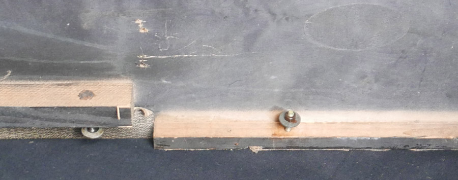
Detail of the shot above. The length of the screw indicates that the piece of timber is unlikely to have been more than 1/2" thick at the fixing point.
Back to the overview page on the single speaker AC30 - 1959-1960.