Vox Vibravox for piano, 1959 - 1960
Vox Vibravox for piano? Perhaps more common than one might expect. The implementation was designed to allow a piano-mounted vibrato control unit and microphone to be linked up to an AC1/15 or AC/30. Below, a picture of the control unit, illustrated in a flyer from late 1959:

Detail from a Vox flyer, 1959. The controls are ON/OFF, Slow, Medium, Fast, Tremolo.
Further details on the outboard equipment can be found on this page. Glen Lambert's page on the history of the Vibravox circuits in JMI amplifiers is here.
In order to allow for the connection of a control unit, the third of the sealed cans containing the Vibravox circuitry, was provided with a plug. The cans, it should be said, were potted with araldite to keep prying eyes at bay - more on that in due course. When the plug was plugged in, the amplifier operated normally, the vibrato and tremolo governed by the controls on the control panel, and the effects switched in and out via the footswitch. When the piano-mounted control unit was plugged in however, via an umbilical cable (what JMI would later call a "cableform"), the control unit then had charge of the effects. Thanks to Glen for spotting what the plug was for.
Plugging and unplugging must have been a real fiddle when the chassis was inside the amp, but not impossible.
Below, a detail of the five-pin plug and socket arrangement for the Vibravox on the chassis of AC/30 serial number 4072 (early Spring 1960). Plug and socket were Radiospares components, part of its "Alldry" series, intended principally for batteries though used in practice for many other applications, as here.
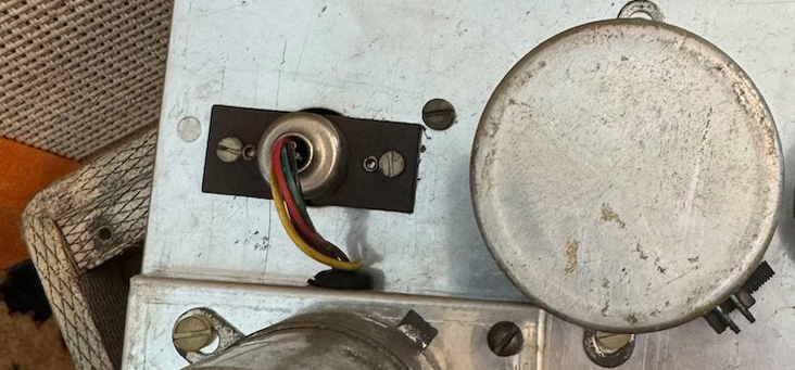
The connections and purpose of the socketed wires - red, purple (violet), green yellow, and black - can be followed on JMI circuit diagram OS/001.

Paxolin board and socket (without zinc "boot").

Plug with zinc "boot".
On the underside of the chassis, the solder terminals of the socket are positioned under the main tagboard, so cannot easily be seen.

Detail of JMI circuit diagram OA/030 for the single-speaker AC/30. The connection points leading to the components in can number 3 are highlighted for convenience.
Below, a general view of the chassis of AC/30 serial number 4072 (early Spring 1960):
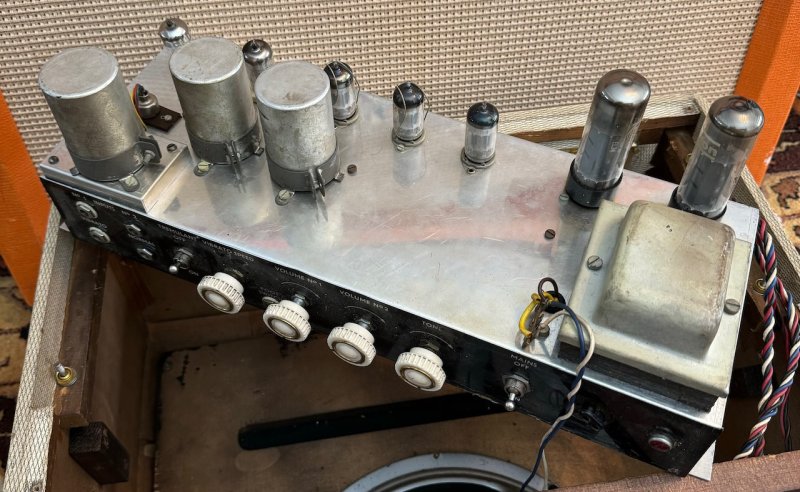
AC/30 serial number 4072.
In "standard" AC1/15s and AC/30s, the three Vibravox cans were normally arranged in a line, rather than in staggered formation:
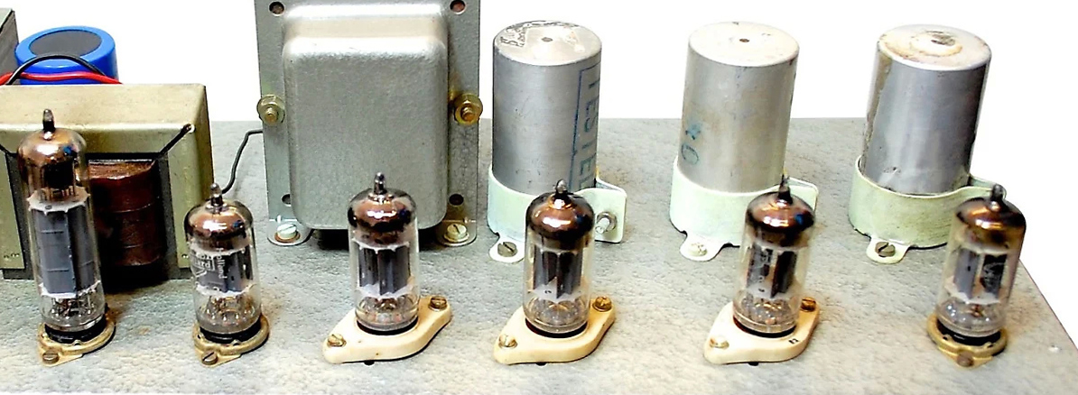
A detail of the chassis of AC1/15 serial number 3708 showing the cans hiding the Vibravox circuitry in line.
Although the amps fitted out in this way must to some extent have been "special" orders, they were not, as it turns out, particularly uncommon. A further AC/30, serial number unknown, can be seen at the foot of this page. There is also an AC1/15 from early 1959. The staggered arrangement of the Vibravox cans on top of its chassis is a giveaway.

AC1/15 chassis, with its Audiom 60 speaker.
It may be that Jennings assembled amps of this kind in small runs (as opposed to waiting for orders to come in). Vibravox cans, made in batches in advance of production, could simply be wired in as needed, no modification required.