
Jennings Organ Company - 30 Watt Amplifier
September 2026
On this page, a Jennings 30 Watt Organ Amplifier, probably from c. 1955-1956, one of two currently known to survive (the other still in place in a "Model A" organ). Derek Underdown later used the circuit - his original design - as the basis for the power section of the single-speaker AC2/30.
He drew from both it and the 50 Watt Organ Amplifier too when he came to design the power section of the Vox AC50 in the latter part of 1963.
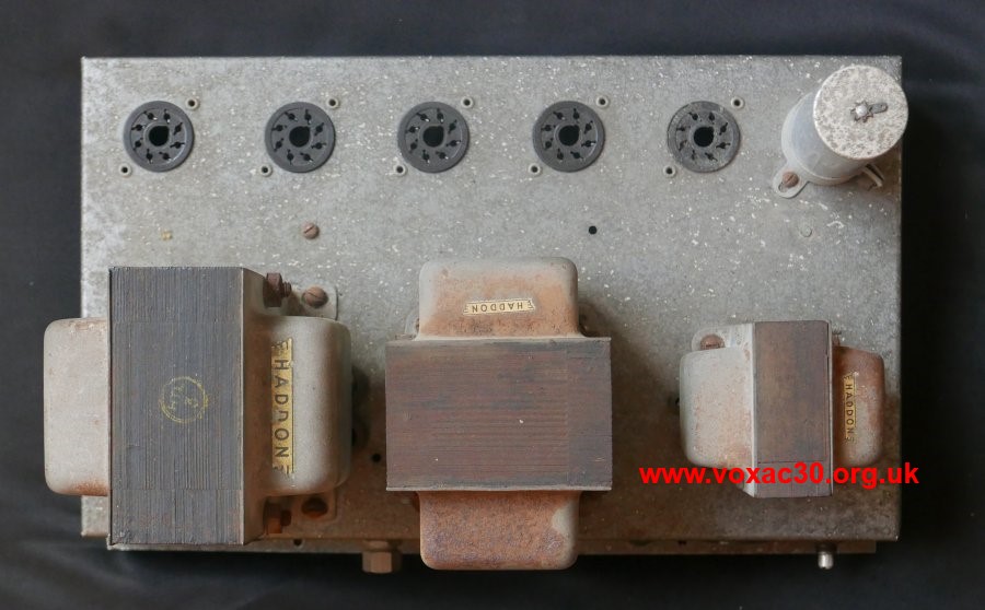
Left to right, Haddon mains and output transformers and choke. As in the case of the Jennings Organ Power Pack no. 3 illustrated a few days ago, valve sockets and other hardware are for the most part riveted onto the chassis plinth.
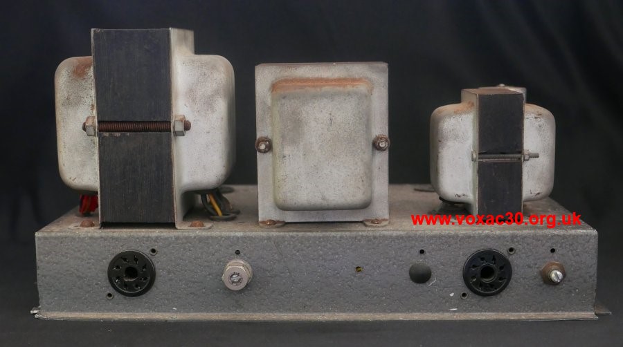
Sockets left to right: mains input and audio out (to speakers); bias adjustment; a blanked off hole (for another pot?); signal in and mains out; volume preset pot.
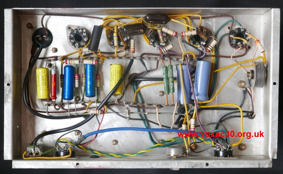
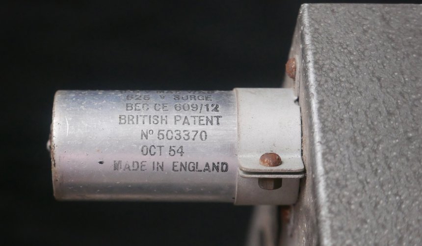
Main filter capacitor, dated October 1954.
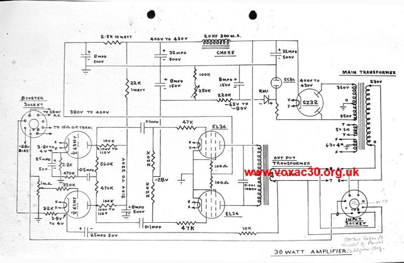
The circuit diagram (drawn by Derek) from a Jennings Organ Company Service Data handbook of 1958. Thanks to Steve for the image. The sheet is undated.
Some facts and figures: the chassis of the 30 Watt Amplifier was slightly larger than that of the Jennings Power Packs it accompanied. It measured: 13 1/8" long; 7 3/4" wide; and 2" tall. Sockets were provided for five valves though the circuit required only four: a GZ32 rectifer, two EL34s, and a 6SN7. The vacant space (corresponding with the fifth socket) can be seen in the photo above. Compare with the shots of the 30 Watt Amplifier in the "Model A" organ pictured below.
The fifth valve socket is completely unwired. It is likely that chassis were prepared in this way to allow for the assembly of a 50 Watt Amplifier, which did require five valves.
Below, a rear view of the Jennings "Model A" organ mentioned above, the 30 Watt Amplifier to the left of the central well for the volume pedal, a Power Pack no. 1 or no. 2, with a heater supply transformer finished in blue hammerite similar to that used for early AC1/15 chassis, to the right. The labour in these organs was naturally the wiring up.
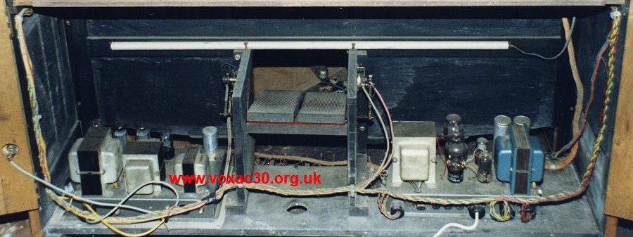
Thanks to Tony, detail from a photo taken in the late 1990s / early 2000s.
A note on the main octal socket on the 30 Watt Organ Amplifier
As one can see from the circuit diagram, the socket served two principal purposes: to bring the mains supply to the mains transformer; and to feed the amplified signal from the output transformer to the speakers.
Some care will have been needed when wiring the (octal) plug up, as the neutral and live lines of the mains transformer were both black, and the "live" and common of the output transformer both green.
Fortunately the pins of octal plugs are numbered to correspond with the numbered solder tags on the socket, but still, wiring up was not a job for the inattentive. Get one wire wrong, and no end of trouble might ensue.
It is likely that JMI had cableform diagrams setting out the detailed arrangement of both socket and plug. Note that reference is made on the sheet below to the "Power Cableform Diag." for the "Model G" organ.
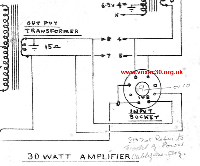
In contrast with the 50 Watt Organ Amplifier, the 30 Watt model had no voltage selector.
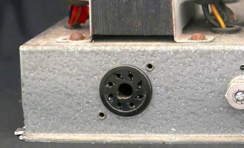
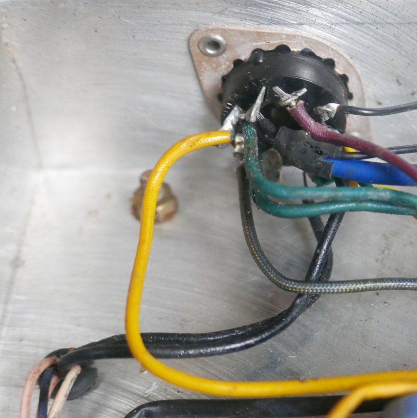
Live and neutral of the mains transformer (disappearing into the chassis pass-through hole) are both black. So for that matter is one of the earths, but that may belong to one of the windings of the secondary.
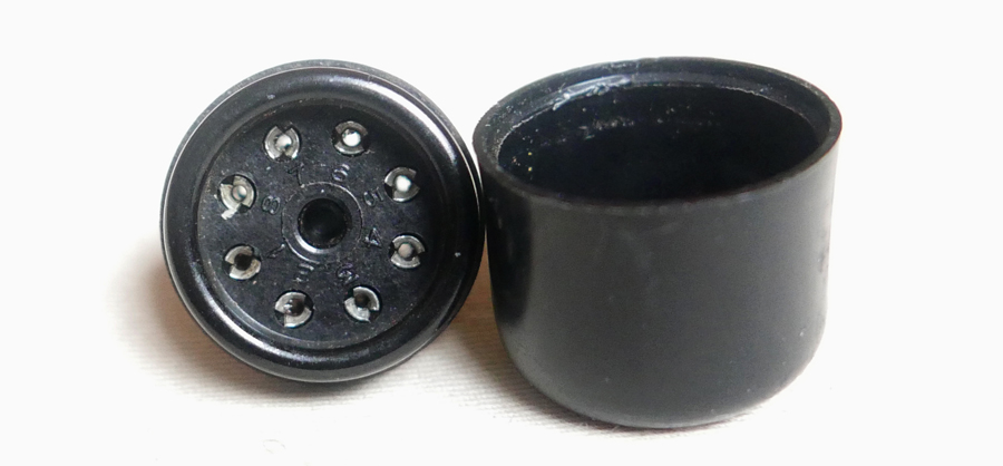
Octal plug with its top off. One can just make out the numbering of the pins on its base.