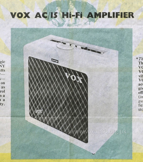
The Vox AC1/15 - first circuit, late 1957 to late 1959
TV Front, 15 watts, two channels (normal and vibravox)

In the latter half of 1957, Dick Denney and Derek Underdown, JMI's design engineer, began work on the "engineering" of the AC1/15 - the amp that Dick had come to Tom Jennings with, still in a fairly basic electronic form, earlier in the year. Mechanical and to some extent cosmetic design were key parts of the process, necessary steps in bringing the AC15 to production.
The first plan, as presented in a JMI brochure released late in the year, was to produce the AC1/15 and AC2/30 as cage amps, the idea being that the chassis could be taken out of their boxes, and with a protective guard over the valves and transformers, used separate from any speaker cabinet. The AC1/15's cabinet was to be similar to the one devised for the AC2/30. In effect the elements were modular. See the material on this page. Modularity was Derek's thing, driven by his work on the design of amplifier sections for the Jennings Organ Company's organs.

A detail from a photocopy of a JMI amplifiers brochure, early winter 1957. The AC2/30 is represented in "cage" amp format, its case below. Text that was feint in the original has been made good.
By late 1957, however, the decision was taken to produce the AC1/15 in a different format - a chassis of its own (ie. of a type different from that of the AC2/30), and an almost square TV front cabinet. Modularity did return in 1959 though with the single speaker AC/30. Early AC/30 preamp chassis, as Jim Elyea has pointed out, were effectively AC1/15 chassis fitted out differently.
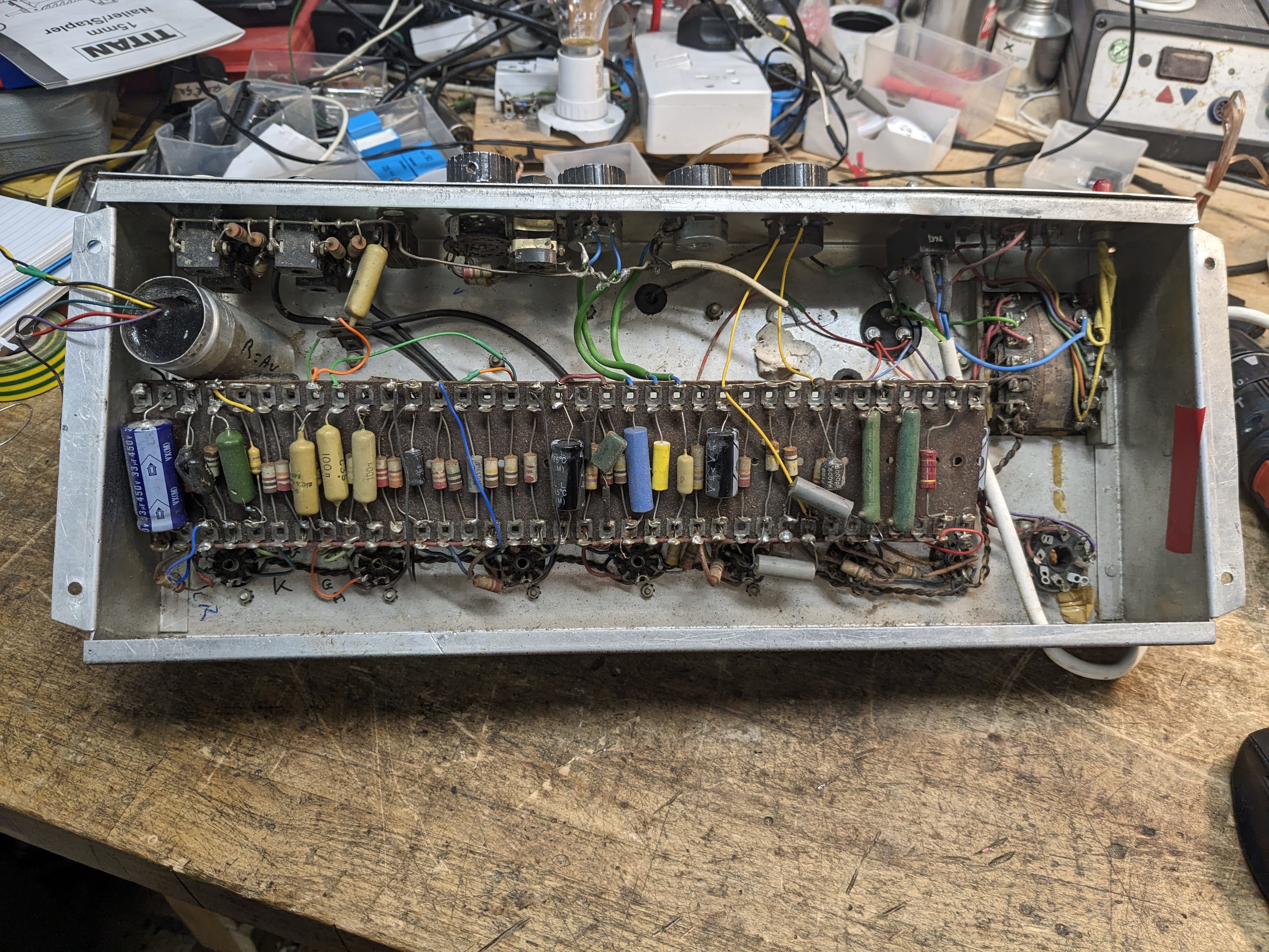
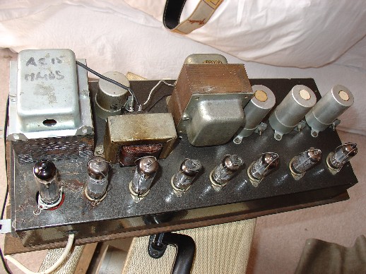
As for the initial design, Derek took as his starting point the chassis he had devised for the power sections of the Jennings "V-series" organs - a rectangular pressed steel box, open at the bottom, with flanges facing out on the short sides (to allow for the provision of fixing points), and inwards on the long (for additional strength). For installation, the chassis was mounted to a board, holes providing ventilation, as in the picture below, and the assembly as a whole then bolted onto blocks inside the cabinet. Note the long slots in the board at top.
The steps required to return the chassis to the cabinet were: (1) bolt the chassis to the board; (2) loosely screw in the top two bolts that hold the board to the cabinet; (3) position the board with chassis attached inside the cabinet (remember the chassis has protruding control knobs and switches); (4) slide the board upwards, guiding its slots onto the loosely attached bolts; (5) screw in, again loosely, the lower pair of bolts that hold the board in place; (6) ensure the control panel is correctly aligned with the cut-out in the cabinet's top, and secure all bolts firmly. The best way to do all this of course is with the cabinet face down on its front.

Serial number 3708, detail of the chassis board in place. The four brass screws hold the chassis to the board.
In general form, the cabinet, with its TV Front, emulated Fender amplifiers of the period, the early Fender Pro being closest perhaps in overall proportions. The AC1/15's cut-out for the control panel was probably copied from Selmer however - no Fender amplifier ever had one. Later it was done away with. More on that to come on the page dealing with second circuit amplifiers (early 1960).
Circuit diagrams
Below, a copy of the first circuit diagram for the early AC15, drawn on 4th March, 1958, entitled "Amplifier Model A.C.1", the sheet un-numbered; and a copy of the diagram for the Vibravox (phase-shifting vibrato) circuit, OS/001. Larger copies of the diagrams will be made available in due course.
In the preamp of the Normal channel, the main driver valve (V1) is an ECC83; for the Vibrato (Vibravox) Channel, two ECC83s and an ECC82 (as a modulator). Early in production, anti-vibration sockets mounted on thick white rubber bases were provided in the preamp for the Vibravox valves. The phase inverter - the valve that drives the push-pull of the EL84s - is an ECC83, configured as a "long-tail pair", the signal being driven through the plates (anodes) of the two triodes contained in the valve envelope.
The topology of the phase inverter remained a standard part of later AC15 circuits (the second circuit drawn up in late 1959, the third in Spring 1960) though many other elements changed.
The power section of the AC1/15, as can be seen from the circuit diagram below, had three valves: a 5Z4 rectifier, and two EL84s. A certain inconsistency seems to have prevailed however in respect to the rectifier - serial number 3730 has a GZ30, and serial number 3745 has a large bottle 5R4.

Jennings Amplifier Model A.C.1 - the AC15, first circuit.

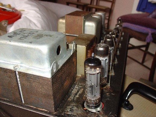
OS/001, undated. The sheet measures 10" x 8", the standard size for JMI small-format diagrams. A second sheet gave the contents of the rest of the circuit, hidden in cans on top of the chassis - disguised to look like capacitors. Note that OS/001 includes the transformer and rectification required for stand-alone Vibravox units. Elements within the section enclosed by the dotted line were not needed for the circuit when built into amplifiers.
A copy of the sheet that sets out the parts of the Vibravox circuit that were sealed up in the cans on top of the chassis will be added soon. The cans, by the way, once populated with components and the necessary feed wires, were filled with Araldite - utterly impossible to remove. Araldite was also used to seal up the tremolo circuitry on the AC10.
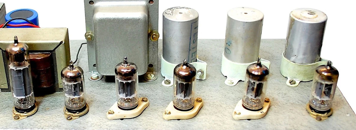
A detail of the chassis of serial number 3708 showing the anti-vibration sockets for the Vibrato Channel valves and the cans behind hiding some of the circuitry.
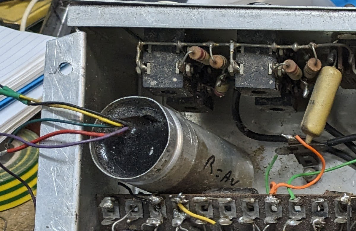
Detail of a Vibravox can potted with Araldite.

Information panel at top left of OS/001. Cans, or rather their contents, could not be repaired. Dartford Road would have to supply or fit a replacement.
A page on the implementation of the vibrato circuitry in Vox amps by Glen Lambert can be found here. Images of the various versions of the stand-alone Vibravox unit are on this page.
Below, a shot of an early JMI wood-block footswitch, in this instance issued with an AC2, but identical in form to the ones provided with AC1/15s to switch the vibrato in and out.
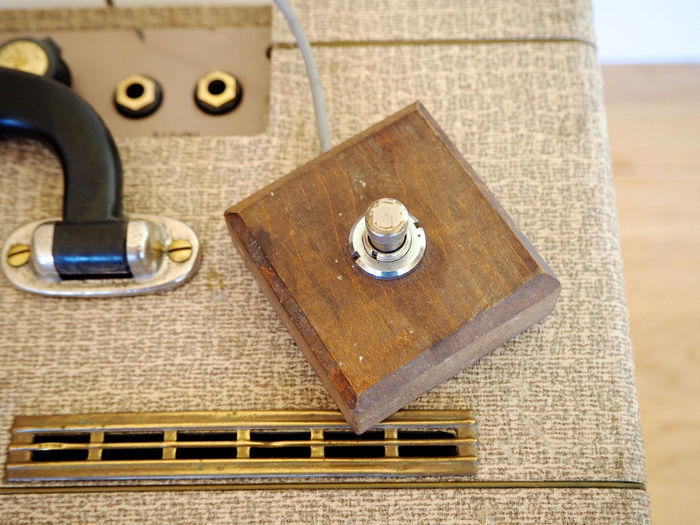
Thanks to Glen Lambert for the picture.
The first circuit revised: November 1958
Below, some illustrative extracts from JMI OS/002, dated 10th November, 1958 - an update and revision to the original circuit. The existence of the sheet has been known for some time but laying hands on an original has taken a while. This copy came in a wallet of circuit diagrams sent by JMI in 1965 to a young man hoping to build his own amplifier.
In terms of the updates: - the voicing of the input stage has been modified to enhance treble responsed; and among other things, plate voltages are given for the EL84s. The nature of the changes to the preamp should help in the dating of any early (relatively unrestored) AC1/15s that turn up.

Date of the revised sheet, signed off by Derek Underdown.

Revised sheet, information panel with sheet number.

Revised sheet, upper right, detail.
Something very strange is going on with the HT voltage: 400v before the choke; 340v after it (!); and 300v after the output transformer (!). The principal question is why start with an HT of 400v if the intention was to provide 300v for the EL84s and around 200v for the preamp - assuming that 400v after rectification is indeed correct?
One answer might be that the transformer was actually designed for a different application - a Jennings organ power pack perhaps - and that Dick and Derek felt obliged to find a use for unused stock. But that remains to be seen. More on transformers below.
Transformers *
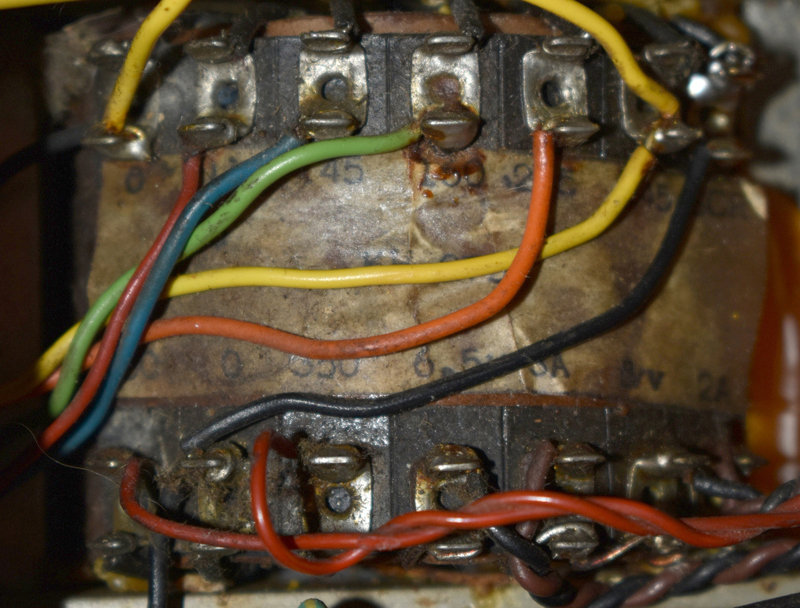
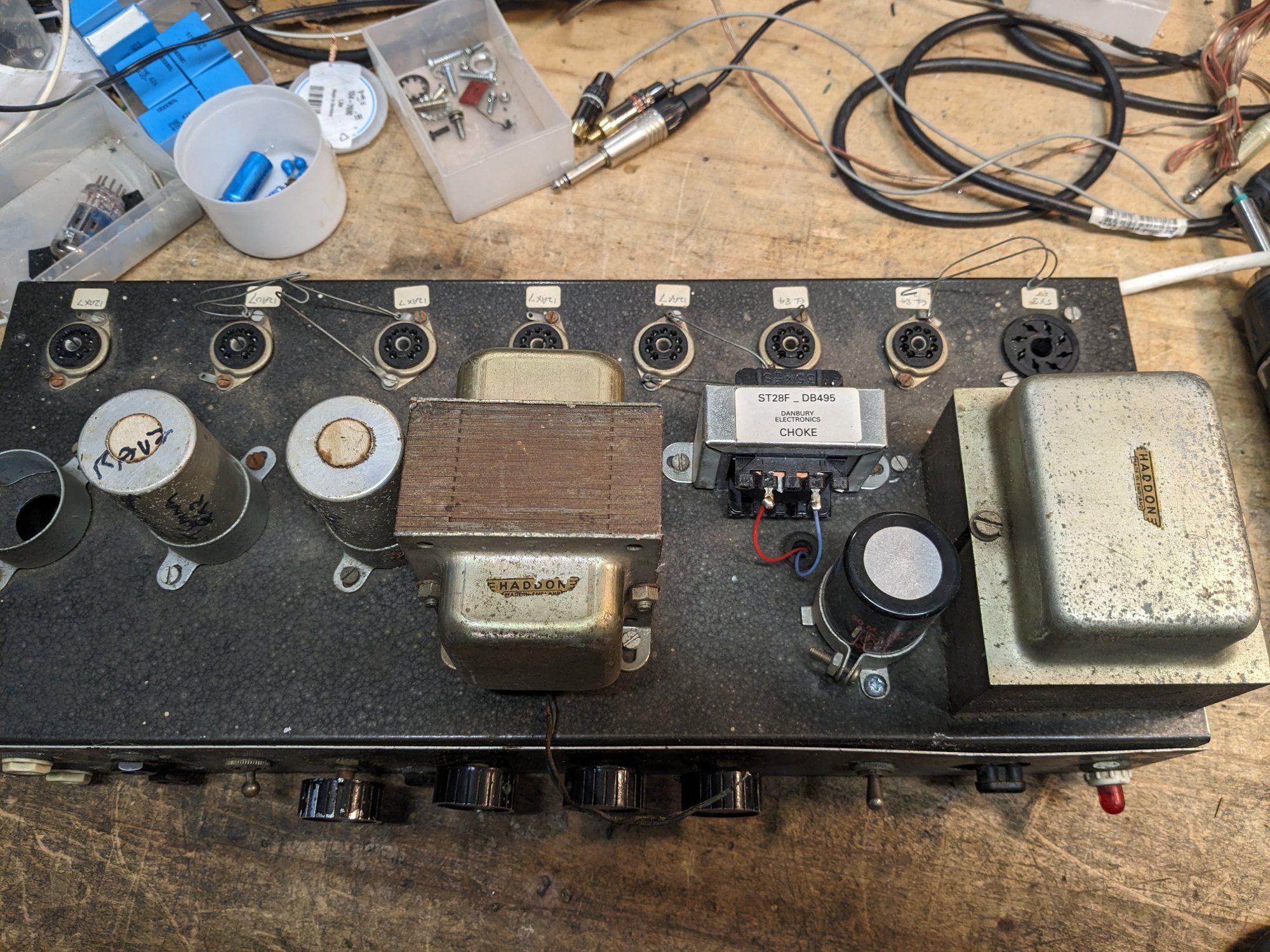
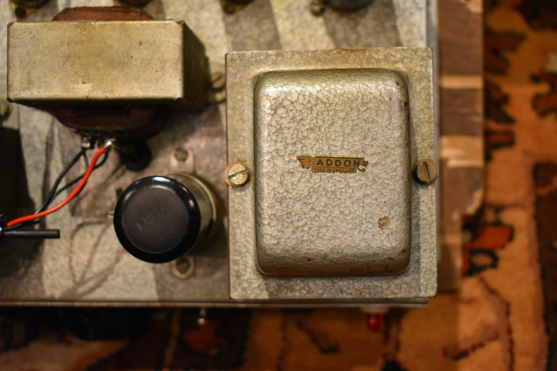
The AC1/15's transformers and choke were produced by Haddon, the company commissioned by Derek to provide transformers for the Jennings "V-series" organs (from 1956 on). Pictures of organ chassis can be seen on this page.

The Haddon logo (missing its "H") on the mains transformer of AC1/15 serial number 3730.

Detail of the AC1/15 first circuit, first circuit diagram (no additions). Note how the HT somehow falls from 400v to 340v after the choke.
As overseas sales were envisaged, provision was made for running the AC1/15 at different voltages. The circuit diagram indicates that the mains transformers was to have had steps at 110v, 130v, 200v, 225v, and 250v. In late 1958 it was reported that AC15s had indeed been sold to America, where the 105v tap on the transformer would have come into its own. See the notice on this page. It should also be said that UK mains electricity varied considerably in the 1950s, from 200v (in Bow, London, it is said) to 245v in other parts of the country. Some areas of Bristol apparently had 210v through to the late 1960s.
When it came to production though, JMI adopted (or perhaps simply accepted) from Haddon at least two types of mains transformer not envisaged in the circuit diagrams.
TYPE 1 (by early 1959)
Transformer in an amp with a serial number in the high 3500s / low 3600s.
SCREEN - 0 - 115 - 145 - 160 - 212 - 237
350 - 0 - 350 - 6.3V - 3A - 5V - 2A
In the centre, what may be the transformer's part number, its first letter hidden - "xL. 113".

Voltage selector of the amp.
The voltages given on the selector are the same as on the selector pictured below: [110/120v], 135/155v, 156/170v, 200/225v, [225/245v].
TYPE 2 (later 1959)
Mains transformer underside, serial number 3730
0 - 115 - 145 - 160 - 215(?) - 245 - SCREEN
350 - 0 - 350 - 6.5v - 6A - 5v - 2A.
The transformer's part number appears to have been "KH" followed by three numbers (obsured by wires in the photo). The voltage selector was printed accordingly. Pairs of voltages are specified, one tap or other in the transformer falling between the two. The pairs are 110/120v; 135/155v; 156/170v; 200/225v (?); and 225/245v.

Naturally the revised taps in the primary rendered the circuit diagram as we have it incorrect - and there is nothing to suggest at present that JMI updated it. Perhaps something will come to light in time. At any rate, it seems unlikely that the changes inconvenienced players too much.
Perhaps the most striking thing about the mains transformer however is its secondary voltage - 350v, rising to 400v after rectification. As Glen Lambert has kindly pointed out, EL84s have a recommended maximum plate voltage of 300v - see the Mullard specification sheet from 1957 on this page. The first circuit AC1/15 will have punished its EL84s mightily.
Indeed, the valve best suited to the secondary voltages produced by these transformers will have been the EL34 - as used in JMI's AC2/30, the later AC/30, and in Derek's organ power sections. As the voltages given in the AC1/15 circuit diagram correspond with those given on the underside of the transformers themselves, it looks as though Dick and Derek were flying by the seats of their respective pants.
Just to add, the mains socket on the AC1/15 - made by Bulgin - was positioned low down on the left hand side (as one views the amp from the front) near the rear edge. Inside the cabinet, the fuse and wires running up from it to the chassis.

Bulgin sockets and connectors will have been unknown in the USA in the late 1950s. Presumably if AC1/15s did actually make it across the pond, US sockets and connectors will have been fitted.
* Thanks to Glen Lambert for his help throughout the section above. Any errors are my own.
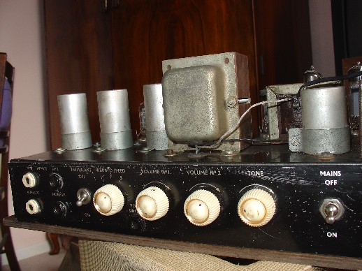
Cabinet fittings
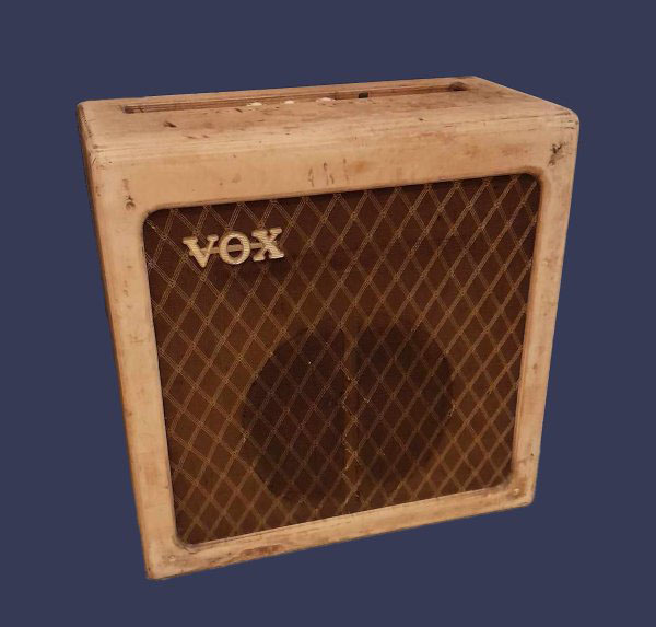
For the time being, the AC15 will be dealt with mainly in terms of circuits and construction. Cosmetics are naturally a secondary thing. It is worth saying at this juncture though that cabinets made in 1958 tended to have white handles (so far around a dozen counted in surviving photographic records). From 1959 one finds black.

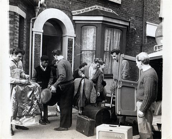
Still from footage shot in late 1958 at the Piccadilly Theatre of Colin Hicks (brother of Tommy Steele) and his band The Cabin Boys. The group had three AC1/15s, the third seen fleetingly in the wings, so presumably a spare. At front of stage are matching cabinets of some sort - proportions much as the AC2/30 rather than the AC1/15.
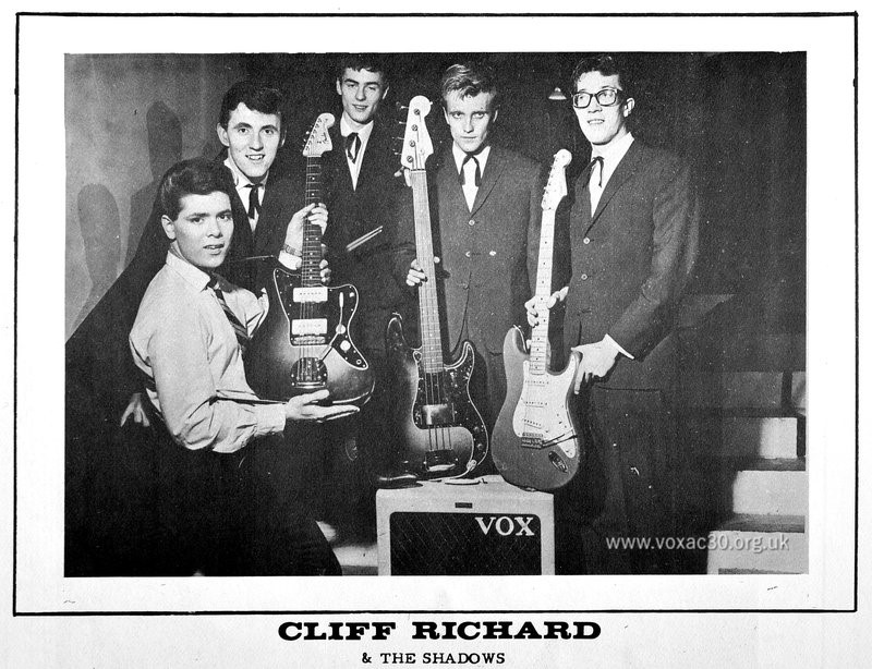
Cliff and The Shadows, the famous early publicity shot - late 1959 / early 1960 - published in a variety of crops. This print is cropped vertically (though only slightly). In view, an early first circuit AC15 (AC1/15) with white handle, the over-size logo added for the photo.
In terms of speakers, one generally finds either blue label Goodmans Audiom 60s (15 ohms) or Celestion alnico G12s, normally designated B024 (8 ohms). Both are rated at 15 watts. The full height back of the AC1/15 cabinet, vented though it was, will have given further headroom.
Surviving amplifiers
Serial numbers are likely to have begun at 3500 [*not 3000 as previously stated]. Amplifiers were assembled - made ready for sale - at the Dartford Road Works (115 Dartford Road, and sheds behind number 119).
Pages on AC15s built to the second circuit and early third will be set up in due course.
If you know of further amps that should be incorporated on this page, do let me know.
Chassis in blue hammerite
Probably the first 50 or 60 AC1/15 chassis. In terms of construction, the aluminium sections were first cut to size; holes were pressed and drilled; the main body and side pieces then "formed" (bent and pressed), and the side pieces riveted into place. The final stage in the process was the spraying with blue hammerite paint - Tom Jennings's choice of colour. In at least one surviving example colour passed through the holes for the valve sockets onto the interior face of the chassis.

Halos of overspray on the interior of the chassis of serial number 3539.
Serial number 3537


Picture from Jim Elyea's superb book, p. 208. Blue hammertone (hammerite) chassis. The output transformer in the centre of the chassis is a replacement, the original having gone.
Updated
Serial number 3539


Recently come to light in the UK. Blue chassis, serial number stamped on one of the flanges. Re-covered at some point with black vinyl that had become extremely ragged, stuck down in places with black tape. That has since been removed. Remains of the original diamond-pattern rexine survive. Thanks to Steve for the pictures.
Further pictures of AC1/15 serial number 3759, currently the earliest fully working Vox amplifier known, can now be found on this page.
AC1/15 serial number 3539.
Serial number 3542


Superb condition externally, the original white carrying handle still present. The Vox logo is formed from wooden letters covered with silver and set on a red background. Hammertone blue chassis, the serial number stamped on the outer lip. The speaker is a Goodmans Audiom 50. Thanks to John for the pictures.
From this point grey hammerite or plain metal chassis
Serial number 3582


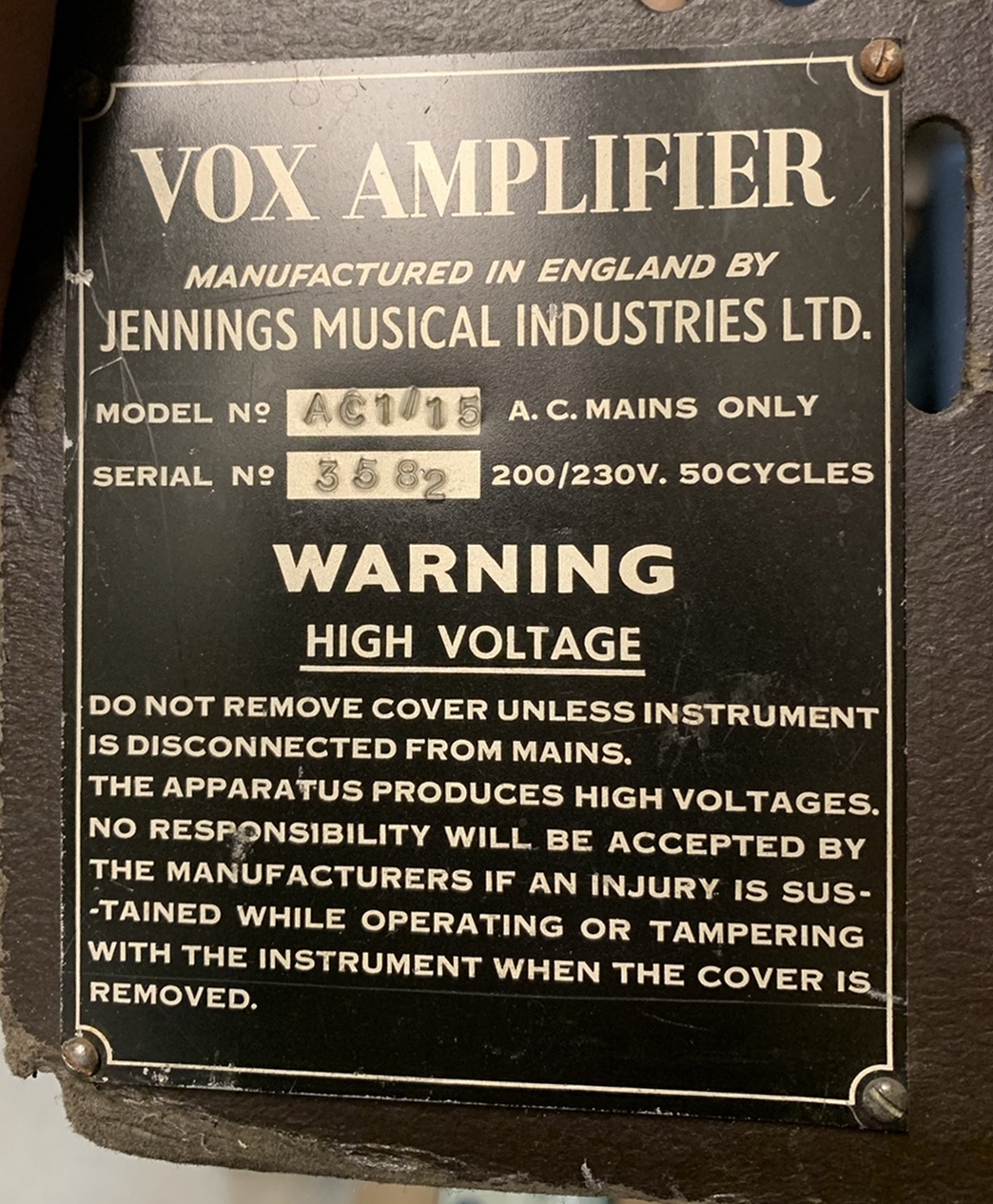
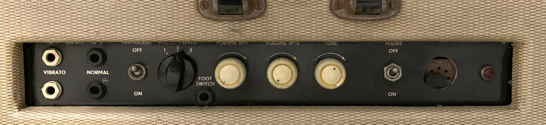
Superb cosmetic condition. The output transformer has been removed; the original anti-vibration preamp valve sockets may have been replaced, though that is not certain. In the preamp, Hunts capacitors with "YAD" and "WID" date codes = 9th and 13th weeks of 1958. One of the green TCC caps has "PH" = August 1958. The black WIMA Tropydur caps have date codes for 1956 and 1958. The speaker is a Goodmans Audiom 60. Black carrying handle. The control knob for the vibrato speed is of the type used on certain Jennings Univox J6 keyboards.


Jennings Univox J6, with "OFF" position. Vibrato on the AC1/15 and the stand-alone Vibravox unit was switched in and out via a footswitch.
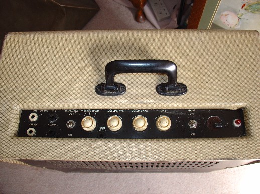
A detail from a Vox flyer for the AC1/15, early to mid 1959 - one can just see the three white control knobs for volume and tone, and the larger black one for the vibrato speed. White carrying handle.
Serial number probably in the low to mid 3600s

Output transformer without shrouds / end bells, as the amp immediately below. The arrangement of the Vibravox cans indicates that the amp could be linked up with Vox Piano Vibrato control unit - see this page.
Serial number probably in the low to mid 3600s


The output transformer is of the same type as the amp in the entry above - no shrouds / end bells. Three sets of pictures, one from its appearance on ebay in the UK in the mid 2000s. A single pic of the chassis post restoration. Two shots from the Dallas International Guitar show, May 2024,
Serial number 3645


As below, chassis painted in dark grey hammerite. The Hammond mains transformer has the designation "031/DT". No component date codes are known at present. The speaker is a Goodmans Audiom 60. Note that the serial number is stamped into the removable hardboard back of the cabinet. Thanks to Steve for the pictures.
Serial number probably in the low to mid 3600s


Chassis in course of restoration. Dark grey hammerite. The black WIMA Tropydur capacitors have date codes: "88" and "108" = August and October 1958, suggesting that final assembly of the amp as whole took place in early 1959. Visible in one of the shots, the Araldite filling of one of the Vibravox cans. Thanks to Steve for the pictures.
Southampton c. 1960, either an AC/15 or an AC/30, both of which were fitted occasionally by JMI with beige/tan grille cloth. Picture from this page.
Serial number 3670

Picture from Jim Elyea's book, p. 354. Said to be Spring 1959. Black carrying handle.
Serial number unknown
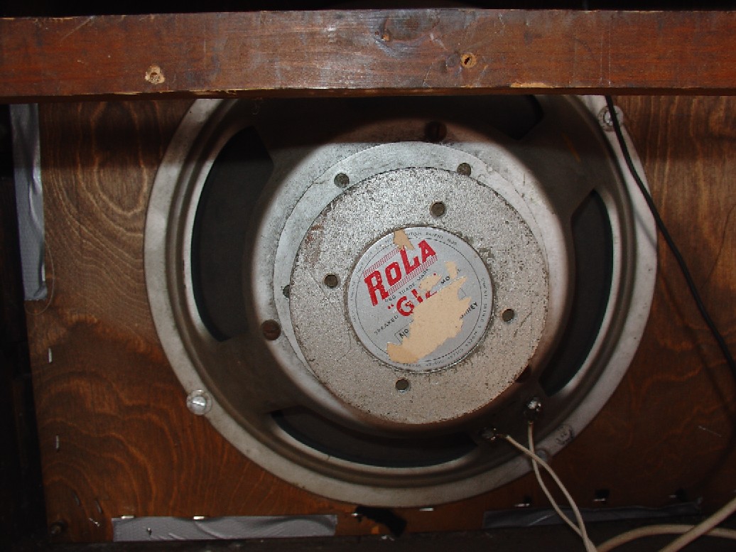
Note the tan grille cloth, as serial number 3670 above. The circuit has been adjusted to take an EZ81 rectifier valve - note how the socket does not occupy fully the hole in the chassis. The cabinet, which contains a species of Rola Celestion G12 alnico speaker, has a pressed board back. Black carrying handle.
Serial number 3708


Cream diamond rexine. Haddon transformers. Three Hunts capacitors have the date code "HWA" = 21st week 1959 (late May); another has "SHD" = 52nd week 1958; and yet another "WTA" = 14th week 1959. The Celestion alnico B024 has "13GD" = 13th July 1959. Black carrying handle. Note - do not attempt to go to the "Soundgas" website, it currently has malicious code on it.
Serial number 3728
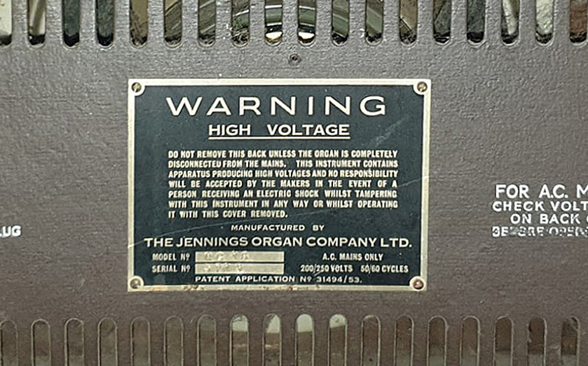
A "Jennings Organ Company" serial number plate, used on console organs (ie. not the Univox) and on certain AC15s with serial numbers in the low 3700s. What is patent application 31494/53? Clearly something to do with organs rather than amplifiers, and applied for in 1953, but no records are presented for this number, or 3149453, in the international super-database of historical patent applications and awards - espace.net. Other early Jennings things are there though.
Serial number 3730


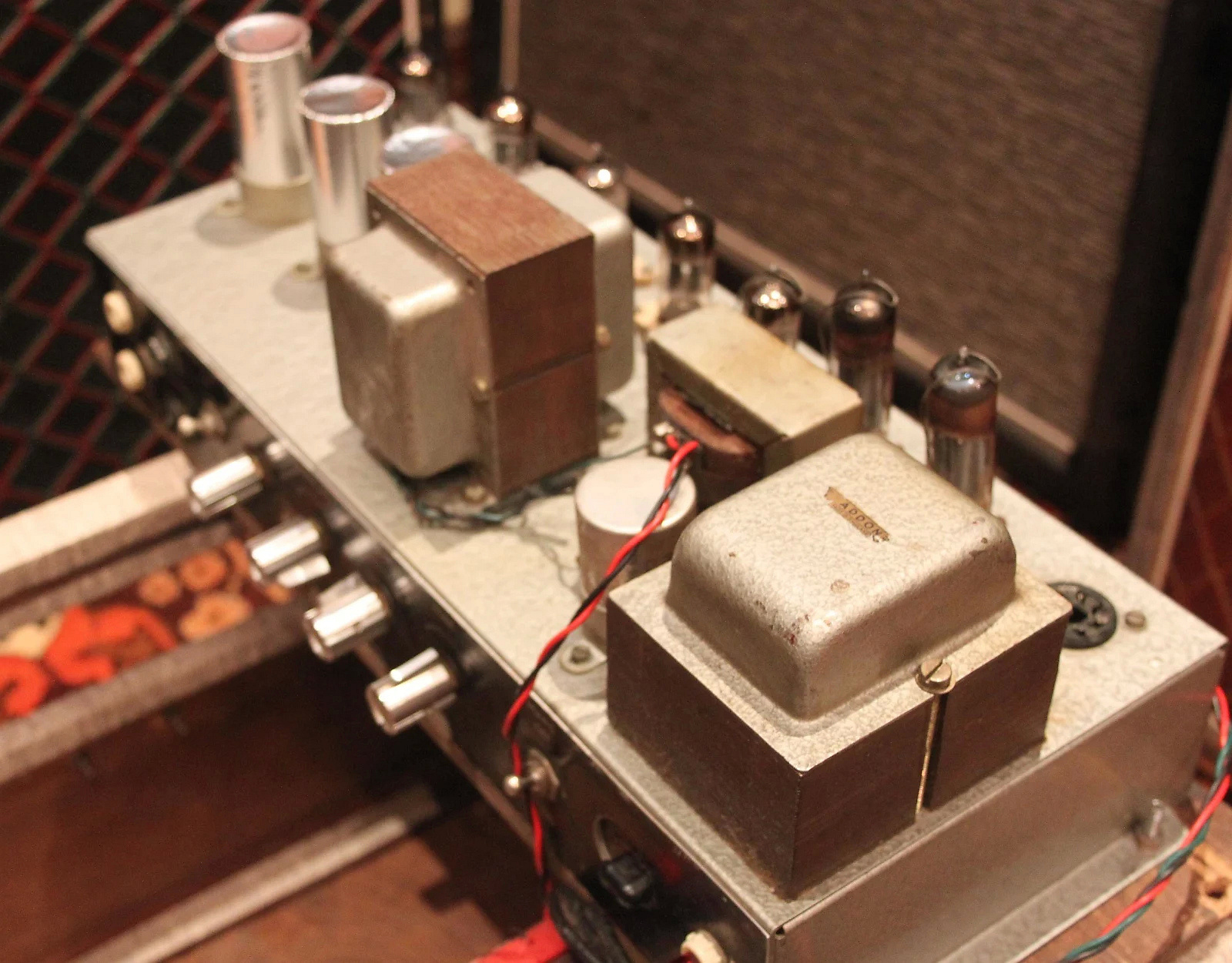


Sold by Musiclocker in 2018, amp, cabinet, and speaker in good shape, the cabinet recovered. Some replaced electronic components (normal for an amp of this date): the cans containing some of the vibrato circuitry have been redone. In the preamp, the blue Hunts 32uf capacitor, far left, has the date code "SHD" = 52nd week of 1958. Note that Jennings's name and address is printed at the foot of of the original pressed board back. Black carrying handle. The Celestion B024 has the date code "09JD" = 9th October 1959.
Serial number 3745


Haddon transformers. The rectifier valve is a 5R4. The original cover survives. In the cabinet, a Goodmans speaker. Black carrying handle. Picture number 4 is from the sale of the amp on ebay some while ago.
NEW
Serial number 3769


Superb condition externally, the electronics (transformers aside) for the most part appear to have been renewed at various points over the past decades. The original speaker may have been a Celestion CT3757. Thanks to Keith for the pictures.
On the control panel, the legend for the Vibrato Speed has a "3" with a flat-headed top, much as on panels for AC/30s (identical layout). Most AC1/15 panels have a "3" with a rounded top. Panels earmarked for AC/30s were doubtless used occasionally for AC1/15s when the need arose.

Serial number probably in the 3700s


Chassis in good order and original speaker still in place, in this instance a Celestion B025. Thanks to Jerry for the pictures.
Serial number 3769
Still the same style of chassis as the examples above. From serial number 3861 one finds the new "Contempo" chassis - cited by Jim Elyea, p. 208.
On to the page on second circuit AC15s - the "AC/15".
A selection of material on early AC15s can be found on this page.