Vox AC30 website updates
March 2021
29th March (2)
A new page has been started on early AC30 circuit diagrams. This will be updated soon.
29th March
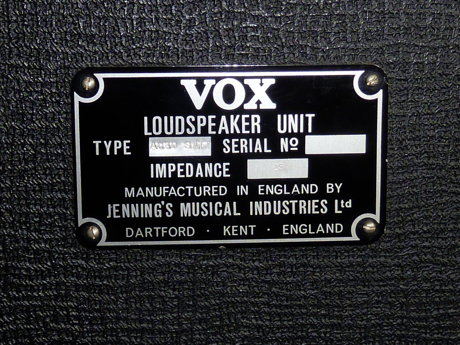
AC30 serial number 18128T, with old-style (1959-1960) "Thirty" flag and part hand-stamped plate. Thanks to Lewis for the pics.


27th March
Serial number 4981N (not 4951 as previously stated), a copper panel AC30/6 (probably from late 1961) in superb condition, is being offered for sale here.
The tone pot has the date code "FI" = June 1961; the main Hunts preamp filter cap "HSW" = 25th week of 1961.
The cabinet has a 3/4" ply top; sides are 1/2", but thickened at front to match the 3/4" of the top. The bottom looks to be 1/2" ply, front and back.
By serial number 5300, Twin cabinets were 3/4" all round at front.

23rd March
Closer examination shows that OS/013 is actually OS/065 copied onto a larger page, the Top Boost circuit added new at top by draughtsman "PG" in 1969. A copy of a copy of OS/065 survives with a caption, perhaps written early on, indicating where the TB circuit was to be added - junction of R10/R11, But the sheet has been trimmed, so it is not possible to be certain of date. A picture to follow.
22th March (2)
Just to add that the sheet illustrated in the previous entry was accompanied by another very feint one, also numbered OS/013, but with hand-written changes to the circuit, and captions for the volume controls. Above the info panel is "Serial No. 9619. Modified." A copy will be posted if the scan can be made legible. The date on the accompanying sheet is 20/11/69.

22th March
Below, a copy of OS/013, the sheet for the Vox AC30 with integrated Top Boost, just arrived. It was drawn out by "PG", who worked for "Vox Sound Equipment Limited" (1968-1969) and afterwards "Vox Sound Limited" (1970-1973). Among other things, he drew out the circuit diagrams for the solid state PA amplifiers - the PA500SS and the PA100SS.
The AC30 TB diagram is likely to been produced c. 1969, ie. in the VSEL period, the name of the company later being changed on the sheet to VSL. In other words, it probably pre-dates the one dated 2nd February 1971, on this page.
Whether OS/013 was copied in part from an older JMI sheet is difficult to say. No JMI circuit diagram for the AC30 with integrated Top Boost has so far come to light.
OS/013's layout is relatively clear, but unusual in being taller than it is wide. The image below is simply to show the main lines of the sheet. A large downloadable version will be provided on the new circuit diagrams page once the diagram has been annotated (to make good a small number of component values that are indistinct).

21st March
A page has been set up on Vox AC30/6 circuit diagrams (schematics). This will be updated soon, as new info is pending.
20th March
Some details coming soon of a further "Vox Sound Limited" circuit diagram OS/013 for the AC30. "Vox Sound Limited" was formed in January 1970 and collapsed in late 1972. In the summer of 1971 production moved from the Erith Works to Hastings/St-Leonards-on-Sea. The diagram is therefore likely to be from 1970-1971.

Note that in the top panel there is a large gap between "Sound" and "Limited". "Vox Sound Equipment Limited", the name of the previous company (1968-1969), originally stood there, "Equipment" having been erased. In the lowest but one panel, the hand-written "Vox Sound Ltd" may have been supplied over the erasure of "Vox Sound Equipment Limited".
The sheet was drawn by the person that drew another VSL diagram for the AC30 dated 12th Feb.1971 - see below, entry for 23rd Feb.
The sheet's number - OS/013 - should on the face of things be a JMI number. OS/011 (redrawn in 1964) is for the JMI Reverb unit; OS/012 (dated 15/09/58) is for a "Jennings Organ Company" V-series organ power section. No JMI sheet numbered OS/013 is known. If OS/013 is not simply a mistake for OS/213, which would certainly be a VSL sheet, then it may be that VSEL or VSL simply used an unallocated number in the old sequence. There are quite a few gaps.
17th March
The etch and fill process - blue/grey panels, 1964 to 1968:
Preparation of the layout (design) was much the same as for anodised panels. The positions and centres of the holes needed for input jacks, potentiometers, etc, would be marked, as before, so the panel could be machine drilled accurately later on.
Once the layout had been finalised and checked, the first stage in the process was the making of a sharp (and clean) photographic negative transparency.
Large sheets of aluminium were coated with a layer of brass. The sheets will have been guillotined into panel-sized units later.
The brass upper layer was coated with a photo-sensitive emulsion, and a light sources directed through the negative onto it. Areas exposed to light - i.e. the captions, lines and so on - became resistant to acid; the other areas (ie. the majority of the panel) remained unprotected. The panel was washed in a solution that only removed the emulsion that had not been exposed to light.
Acid was then applied to etch away the areas of exposed brass. The legends and elements of design (still protected by emulsion) were left in high relief.
Epoxy enamel blue/grey colour was then sprayed onto the panel, filling up the sunken portions almost but not quite level with the surface of the legends.
Once the blue/grey colour had hardened and dried, silver colour was rollered across the panel's surface, touching only the raised letters, lines and so on.
The panel was then cleaned and checked. Holes for the input jacks, potentiometers, and other hardware, were machine drilled, removing the marks provided for centring.
15th March (2)
ANODISED PANELS - an overview of manufacture: black with gold legends; copper with silver. Black panels were double anodised; copper panels, single. In the case of the former, the second anodisation added the gold colour to lines and legends.
In the days before Letraset (1960-1961), captions, logos, lines, and so on, would be printed up on paper, actual size, by a printer, and the layout would be created by careful cutting and pasting.
Layouts included positions and centres of the holes needed for input jacks, potentiometers, etc, such that the panel, once anodised, could be machine drilled accurately.
With the advent of Letraset in 1960-1961, layouts will have become much easier. Letraset not only provided letters and numbers, but lines, curves, circles, and so. The principal font used by JMI was Futura Bold.
(1) Once the layout had been finalised and checked, the first stage in the process was the making of a sharp (and clean) photographic negative transparency.
(2) The specialist panel maker might either prepare panels individually, or laid out as multiples on a single large sheet, to be guillotined at a later stage in the process.
(3) The surface of the aluminium was coated with a layer of photo-sensitive emulsion, and a light source directed through the photographic negative onto it. Areas exposed to light - i.e. the captions, lines and so on - became insoluble in water/developer; the other areas (ie. the majority of the panel) soluble. The emulsion that remained was also resistant to the acid used in the anodisation process.
(4) The aluminium was then immersed in the anodising bath - an electro-chemical (electrolytic) dip, direct current passing through a solution of sulphuric acid. The process made exposed areas of the metal - those not protected by the emulsion - porous to dye. Elements of the design were protected by the acid-resistant emulsion.
(5) Panels were washed in distilled water, then immersed in or sprayed with the dye. They were washed again with distilled water and then boiled for around 15 minutes to seal the colour.
(6) The emulsion protecting the design was removed at this point, leaving legends, lines, and positioning marks in bare, un-dyed, aluminium.
(7) Black panels would be anodised a second time to add gold colour to the bare aluminium of the legends.
(8) If larger sheets had been anodised, individual panels were cut out. Holes for the input jacks, potentiometers, and other hardware, were then machine drilled, thereby removing the marks provided for centring.
Details will be added to the page on AC30 panels. An overview of the etch-and-fill process used to create the blue/grey panels will be posted soon.
15th March
Thanks to Johnny, AC30 Super Reverb Twin serial number 5262, a top boost model, is now registered.


15th March
Thanks to Dean, pictures of serial number 5619 - a bass model, late 1962, assembled by Burndept for JMI.


8th March (3)
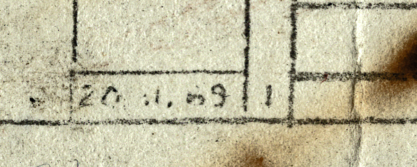
A strange pair of blues, repaired in 1971. The one on the right - date code "10GH" = August 1963 - has an unused set of holes for solder terminals in its frame. The one on the left - a T1088, date code "30MJ" = 30th Dec. 1964 - has an added terminal strip.


8th March (2)
Just to note that late in 1964, Celestion blues - or at least certain units - were classified as T1088s rather than T530s. Below, an example with the date code "18JJ" = 18th September 1964. A blue also survives, stamped T1088, with the date code "30MJ" = 30th December '64.


8th March
A note on split-front AC15s. Pictures that have just emerged - thanks to Marc - show that fawn split-front AC15s had certainly been introduced by serial number 4212, if not before. From number 4212 to at least 4499, the speakers fitted were hammertone/oyster C3757s or early hammertone/oyster T530s. The earliest examples of the latter to survive with Vox labels are from around June 1960.


A hammertone/oyster T530 from an AC15, date code "21FE" = 21st June 1960.
7th March
Some new material from the US coming soon (relevant items also to be added to the pages on the Vox AC100 website). For the time being, an ad placed by the Music Center, Louisville, Kentucky in the "Courier Journal", 29th August, 1965. In the background, a typically anachronistic Thomas Organ promotional poster featuring The Beatles - a photograph taken in the summer of 1963 with their AC30s. Paul's Super Twin was new at the time, replacing his T60.
For anyone attending a Beatles concert in the USA in the autumn of 1964 and 1965, or for that matter watching newsreel footage in the cinema or on TV, AC30s will have been altogether absent. From August 1964, it was AC100s all the way.
Thomas got into gear with its adverts however in the latter part of 1965. Dealers naturally took a little while to follow.

"Courier-Journal", Louisville, Kentucky, 29th August, 1965. By 1975, the Music Center had either closed or moved.
Thomas also used the pic of The Beatles in catalogues; adverts ("Downbeat" and "Boy's Life" magazines); for a set of dealer photos; on warranty cards; and so on, endlessly repeated and reprinted until around 1966.
Below, a copy of the original photo, taken in the summer of 1963. JMI used the picture in a flyer soon after it had been taken. It was also chosen for Christmas Show programme, 1963, but not much used in the UK thereafter.

Note that the chrome stands are of the new type, with lugs to retain the amplifier, rather than a "tray". These doubtless arrived with Paul's new Super Twin amplifier section.

Beatles Christmas Show programme, 1963. It was during the Christmas concerts that the advert became obsolete. In late December, Paul received an AC80/100, John and George AC50s.
Photos of other English bands were recycled in the same way, the pic of Freddie and the Dreamers, below, entry for 28th February, being one.
6th March (2)
A rare Super Twin cabinet with full valance front from late 1966 or early 1967. Note the new-style logo (as used on cabs belonging to the solid state range). To judge from survivals, a batch of these cabs, accompanied by Super Twin amplifier sections, was exported to Germany. None has turned up so far in the UK.
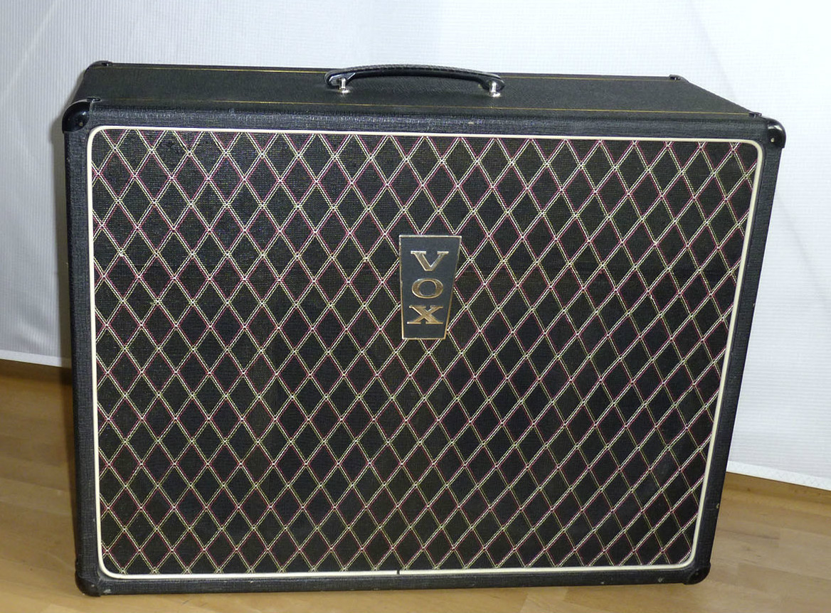
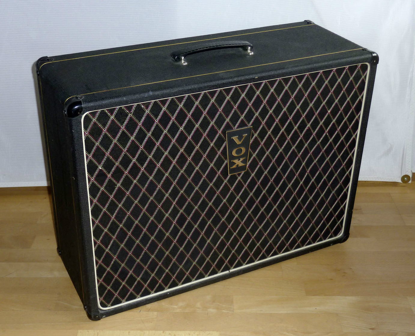
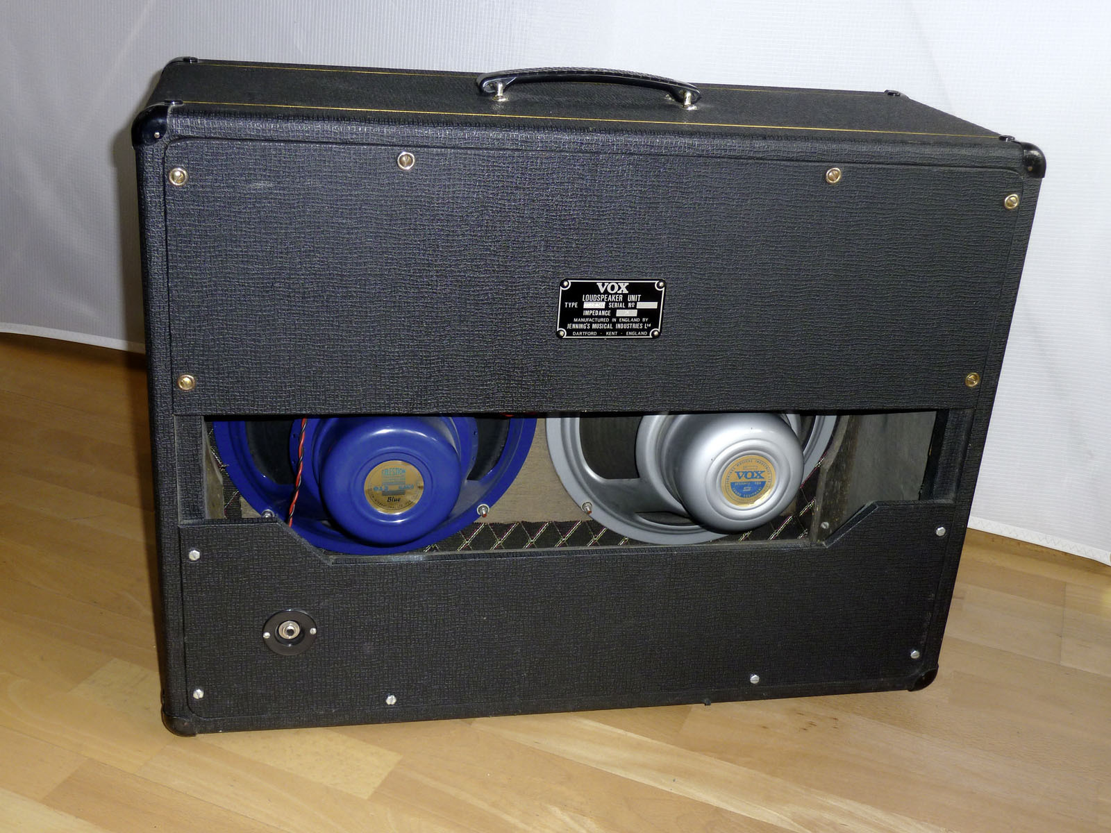
The Celestion blue is a later replacement.
6th March
A quirk of certain chassis assembled by Westrex in 1964. Thanks to Glen for the info.
In at least one instance, the positions of two resistors at the anode of V9, the ECC83 vibrato oscillator, were reversed: R60 and R61 in circuit diagram OS/065. In practice, the error did not affect the circuit in too detrimental a way as the resistors in question are relatively close in value. But it is something that escaped the notice of "quality control" checkers.

Detail from OS/065.

A chassis assembled by Burndept. The 270K resistor (with red/purple/yellow bands) - immediately to the right of the gold-coloured TCC capacitor - is in the correct position.
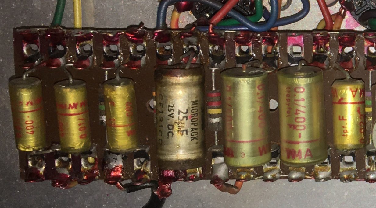
Serial number 10348, assembled by Westrex. Immediately to the right of the TCC cathode bypass capacitor is the 220K resistor (red/red/yellow bands).
3rd March
There are two errors in the entry below, one in the report of 1965, one mine. The report says the JMI AC10 Super Twin's speakers [not the AC30's as initially stated] were "incorrectly wired in series". It should have said they were incorrectly wired in parallel.
Two 8ohm drivers wired in series = 16ohms (correct). Two 8ohm drivers wired in parallel = 4ohms (incorrect).
2nd March
Below, part of a report of Dick Denney's time at the Thomas Organ facility in Sepulveda, north Los Angeles, in October 1965, published in the "Vox Story", Denney and Petersen (1993), p. 144. In the course of comparing the new all-transistor Vox Berkeley II Super Reverb with the "Jennings Berkeley" - the rechristened JMI AC10 [not the AC30 as initially stated] Super Twin Reverb - it was discovered that the latter's speakers had been wrongly wired up, presumably at factory.
Wiring the two 8ohm speakers in series would result in a total impedance of 4ohms, instead of the desired 16ohms wired in parallel. [This needs to be reversed, see the entry above].

Vox Story", Denney and Petersen (1993), p. 144. "Rola" speakers are Celestion (Rola Celestion).
1st March
A page has now been started on the smaller Vox PA amplifiers, principally the Metal Clad 30 (M.C.30). There is some more to add by way of documentation. That a surviving example should eventually materialise....
Updates for October and November 2020.