The Vox AC/15 - second circuit, late 1959 to Spring 1960
TV Front still, 15 watts, two channels
In progress: March 2022

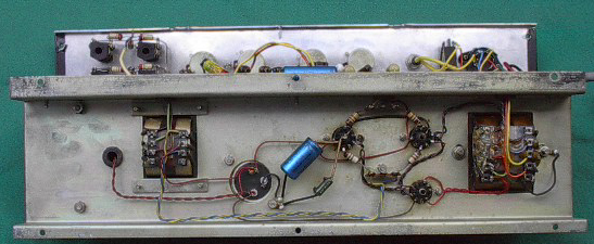
AC/15 serial number 3962, early 1960. The new chassis - steel plinth and folded aluminium preamp upright. Note the positions of the EL84s and EZ81.
Three steps forward, one back. A new circuit; a new chassis; a better form of cabinet; but no phase-shifting vibrato, only tremolo, the controls (and some of the tremolo circuitry) relegated to a "break-out box" mounted in a cut-out on the upper back panel. The unit plugged into a socket on the preamp tag-board.

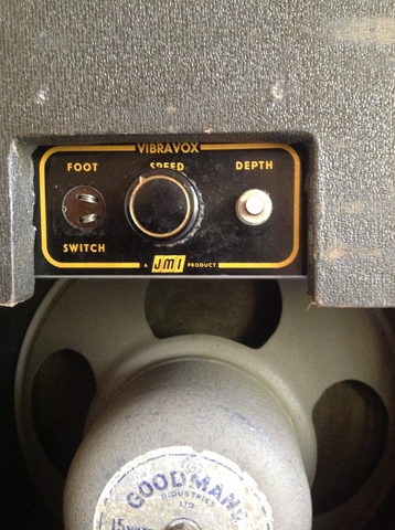
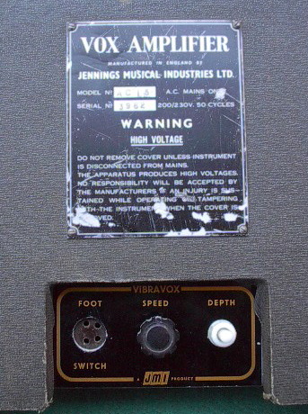
Detail of the tremolo ("Vibravox") box.

Detail of the socket for the "Vibravox" box on the preamp tag-board.
The new form of chassis, mounted on a slider board and with controls facing upwards at back, enabled the island cut-out of the AC1/15 cabinets to be done away with. Chassis and board, supported on runners, could simply be slid out - a huge advantage both to the serviceman and any player who was able to replace valves for him or herself. The cabinet with island cut-out was retained for the single speaker AC/30 for some months more however - until around May 1960, when the new AC30 Twin came into being.
Probably only around 200 amplifiers were built to the second AC15 circuit, a good proportion issued in cabinets done out in two colours of vinyl - bluish grey and "oatmeal", and bluish grey and red being the most common. Cabinets for early third circuit amps were also done out like this - the only way to tell which circuit these amps were built to is from the chassis. Third circuit chassis were arranged differently.
At least one second circuit AC15 (in a cabinet covered with cream-coloured diamond-pattern rexine cloth) seems to have been issued without tremolo. There is no socket for the control box on its tagboard. Whether this was late or early in the run is unknown.
The matter of whether the second circuit AC15s were in some way "transitional" on the path to circuit no. 3 (OA/031) or "experimental" is difficult to assess. The EF86-driven channel will have been considerably better than either channel of the AC1/15; the vibrato effect less good. Around April 1960 the price of the AC/15 went up from 59 to 65 guineas, a ten per cent increase, or thereabouts. It may have been adverse opinion that prompted Dick and Derek to embark on the development of circuit no. 3.
At any rate, by April 1960 JMI had started building amplifiers based on OA/031, the third circuit, offering a BASS version. Presumably at this point, or close to it, production of the second circuit amps came to an end. No second circuit BASS AC15s are known. It is probably worth adding that bass voicing was developed initially for accordionists, not bass guitarists: -

Detail of an advert placed in May 1960. In April 1960 the price given for the AC15 BASS was 70 guineas, 5 guineas more than the standard model.
A page on the AC15, third circuit, Spring 1960, is currently in preparation. In the meantime, details relating to the the "AC1/15", the AC15 of late 1957 to late 1959, can be found here. A selection of material relevant to the AC15 in the 1950s and early 1960s is being gathered together here.
The circuit
Below, a copy of the second circuit diagram for the AC15, drawn on 4th December 1959, entitled "AC/15 Amplifier no. 2", the sheet numbered OS/005. Note the position of the back slash in the model designation - also given in this form on serial number plates. The single speaker AC30 at this time was the "AC/30", and the AC10 the "AC/10".

OS/005, dated 4th December 1959. The sheet measures 10" x 8", the standard size for JMI small-format diagrams.
"Channel I" is the EF86-driven channel with Vibravox (tremolo) - white input socket on the control panel. "Channel II" is the Normal Channel driven by the triode side of the ECF82 - input sockets black.
Note that on the circuit diagram "Channel I" is the Normal Channel, and "Channel II" the EF86 ("Vibravox") channel.
Below, a copy (made in two sections) of Derek Underdown's schema for the physical layout of the tremolo circuitry for the AC15 and AC10. The sheet has no number but is dated 8th April 1960.

"Vibravox no. 2". Derek Underdown's schema for the AC15 no. 2 and AC10 tremolo circuitry, the sheet drawn on 8th April 1960. The black band across parts of it is sellotape.
Larger versions of the sheets above will be provided in due course. It should be said that a circuit diagram for the AC/15 no. 2 survives with the tremolo circuitry incorporated - drawn by Derek, un-numbered, dated 4th December 1959 (as OS/005).
The signficant changes to the circuit are: the introduction of an EF86 valve (of much higher gain than an ECC83) as V1; an ECF82 as V2, mounted in an anti-vibration socket with thick white rubber base, the pentode half of the valve serving the tremolo effect, the triode for the input stage of the Normal Channel; a mains transformer giving a much lower secondary voltage (300-0-300 instead of 350-0-350); and heavier filtering after the EZ81 rectifier (also new) in the shape of a capacitor-choke-capacitor node. The phase inverter however - V3 - is still configured as a long-tailed pair, as in the AC1/15. The value of the cathode bias resistor for the EL84s remained at 130 ohms.
Also important to note: (1) All four inputs have 220k grid stopper resistors. These are wired in such a way as to give the two inputs in each channel the same level of gain - i.e. there are no "high" or "low" inputs.

Detail of OS/005, December 1959.
(2) 100 ohm plate resistors were introduced as a means of giving some protection to the EL84s (to reduce the still high HT). The AC15 first circuit (late 1957 to late 1959) had none. Thanks to Glen Lambert for these points.
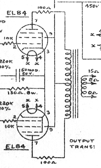
Detail of OS/005, December 1959.
For a more extensive analysis of the AC15 second circuit, used also for AC10s, early 1960 to late autumn, see Glen Lambert's page here.
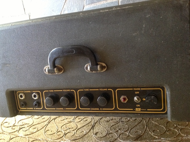
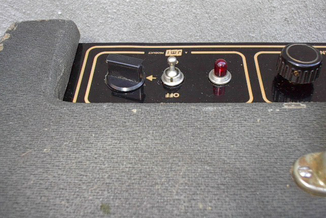
Sales in the USA evidently seem not to have been envisaged. The mains transformer has taps only for 200v, 230v and 250v, accompanied by a new style of three-position voltage selector on the control panel.

Three-position voltage selector. Note that where the circuit diagram gives 230v and 250v, the selector gives 220v and 240v.
Glen Lambert's analysis of the circuit and its tremolo can be found here.
Araldite
JMI was understandably protective of its vibrato circuit, concealing the components in cans potted with Araldite. "Vibravox no. 2" circuitry received similar treatment.

Detail of Derek Underdown's schema for the Vibravox no. 2 circuit.

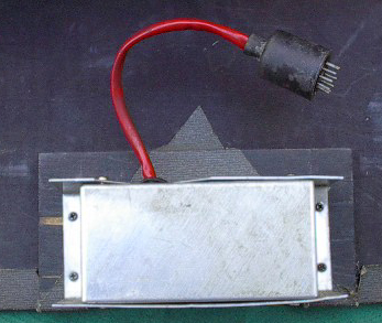
Front of a tremolo ("Vibravox") box removed for repair. The noval (nine-pin) plug on the red umbilical mates with a socket on the preamp tagboard. Note the type of control knob, as used on some early AC1/15s and stand-alone Vibravox units.

Rear of a tremolo ("Vibravox") box removed for repair. The amp to which the unit belongs has pots with date codes "AH" = January 1960.
The two pictures above come from this page. The potting is impossible to remove without destroying the components inside. Araldite, it should be said, was also used by JMI in its guitar-building activities, but as an adhesive rather than a means of concealing things.
Chassis, cabinet, and speakers
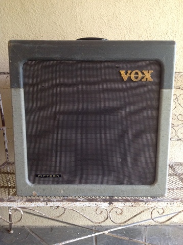
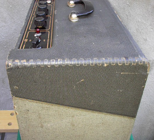
The main body of the cabinet for the AC/15 is much as the cabinet developed for the AC1/15: TV Front, right-angle corners at back, single carrying handle, and so on. The principal differences externally were the different types of vinyl and cloth used as covering, and the absence of a mains socket on the left-hand side. The mains cable of the new chassis issued directly from the amplifier. The single full height pressed board back (with vents in rows) gave way to a new semi-open two-piece back, the boards of birch ply.
Inside the cabinet, runners were provided to support and guide the slider board of the new "Contempo" chassis. Gone was the old block and bolt system of fixing the chassis in place.
The new chassis of the AC15 no. 2 was devised by Derek such that it should (1) sit flat on its slider board in the cabinet, controls facing upwards at back; (2) enable the preamp circuitry to be separated from that of the power section, the aluminium of the upright providing a good shield against electro-magnetic fields; (3) give better support for the transformers (fixing points both on the plinth and the aluminium upright); and (4) create more space for components. The chassis of the AC1/15 is cramped and inconvenient in comparison; and when mounted in the cabinet, its transformers pull down on their mounting bolts.
Slider boards have a cut-out for the tremolo circuit control box (which was mounted on the back panel).

Speakers for the most part are, as before, blue label Goodmans Audiom 60, power handling 15 watts, 15 ohm impedance.
The Shadows
Below, a detail from a shot of Cliff and the Shadows at the London Palladium, probably November 1959, just possibly January 1960. Partially in view at left, a Jennings promotional/demonstration AC15 with larger than normal logo - see this page for other instances.

At various points in 1960 the Shadows are seen with three standard AC15s, a white/beige amp with diamond rexine, presumably first circuit; and four two-tone second circuit AC15s, three with standard diamond grille cloth, a fourth with plain cloth. More on these amps to come.
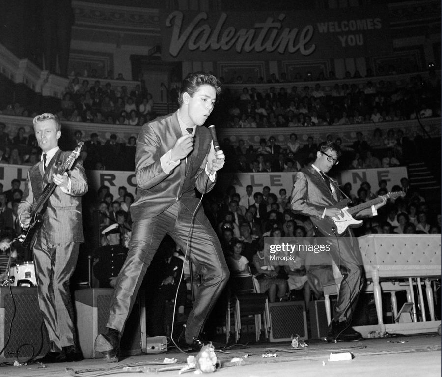
Detail of a picture from Getty Images of Cliff and The Shadows, 18th September, 1960. At left, two of the two-tone second circuit AC15s belonging to the Shadows, and at right a third, all with diamond grille cloth. Shots taken at the Royal Variety Show rehearsals, May, 1960, show the tremolo controls on the rear panel and the Goodmans Audiom 60 speakers.
Surviving amplifiers
Serial numbers generally fall in the range 3800-4000. Probably only around 200 produced. Plates (and circuit diagram designate the model as the "AC/15". If you know of further amps that should be incorporated on this page, do let me know.
Known pot codes on two amps are "AH" and "BH" = respectively January and February 1960. By April 1960, JMI had begun offering a BASS version of the AC15 - never an option for the second circuit AC15 - so presumably it was at this point that production of the second circuit amps came to an end, though how quickly we do not know at present.
Serial number 3861
Noted by Jim Elyea, p. 208.
Serial number 3863
Currently in Germany.
Serial number 3884
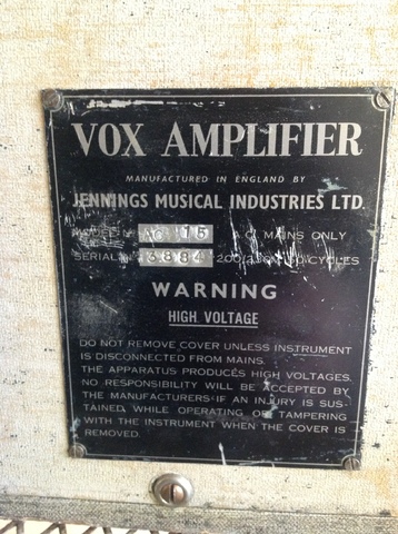
Good external condition. Blueish grey / oatmeal covering; plain dark grille cloth material. The original Goodmans Audiom 60 still in place.
Serial number 3910
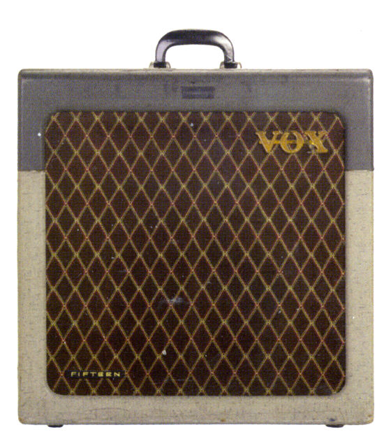
Two-tone greyish blue / oatmeal. Plain cloth, as below. The "FIFTEEN" runner survives lower left on the grille. Two pictures be found here.
Serial number unknown

Two-tone bluish-grey / oatmeal vinyl; plain loose weave grille cloth. No bronze Jennings badge or "FIFTEEN" runner on the front.
Serial number unknown

Two-tone bluish-grey / oatmeal vinyl; plain loose weave grille cloth, apparently darker than the amp above. No bronze Jennings badge or "FIFTEEN" runner on the front.
Serial number unknown

Probably originally as the amps above, but racing stripes added, and the lower section of vinyl redone. Bronze Jennings badge and "FIFTEEN" runner on the front.
Serial number 3962


Two-tone blueish grey blue / oatmeal vinyl; brown diamond grille cloth. The speaker is a Goodmans Audiom 60 (15 watts, 15 ohms).
Serial number 3963
Illustrated by Jim Elyea, p. 354. Two-tone bluish-grey / oatmeal vinyl; brown diamond grille cloth, as 3962 above. Note the bronze Jennings badge, top front.
Serial number unknown


On to the page on the third circuit AC15 (mid 1960 on).
A selection of material relevant to the AC15 in the 1950s and early 1960s is being gathered together here.