Vox AC30 website updates
March 2024
29th March
Thanks to Colin, pictures of an AC30 made by Dallas (still "Dallas Musical Limited") in 1974. The serial number is 7409D1135, the lowest encountered so far. "74" is 1974, "09" is September, "D" obviously for Dallas, and "1135" the number of the amp in sequence. It is likely that this particular sequence began at 1000. In 1975, Dallas changed the format of its numbers at least twice. The next earliest amp currently known is 7409D1183.
The page on early Dallas-made AC30s can be found here.
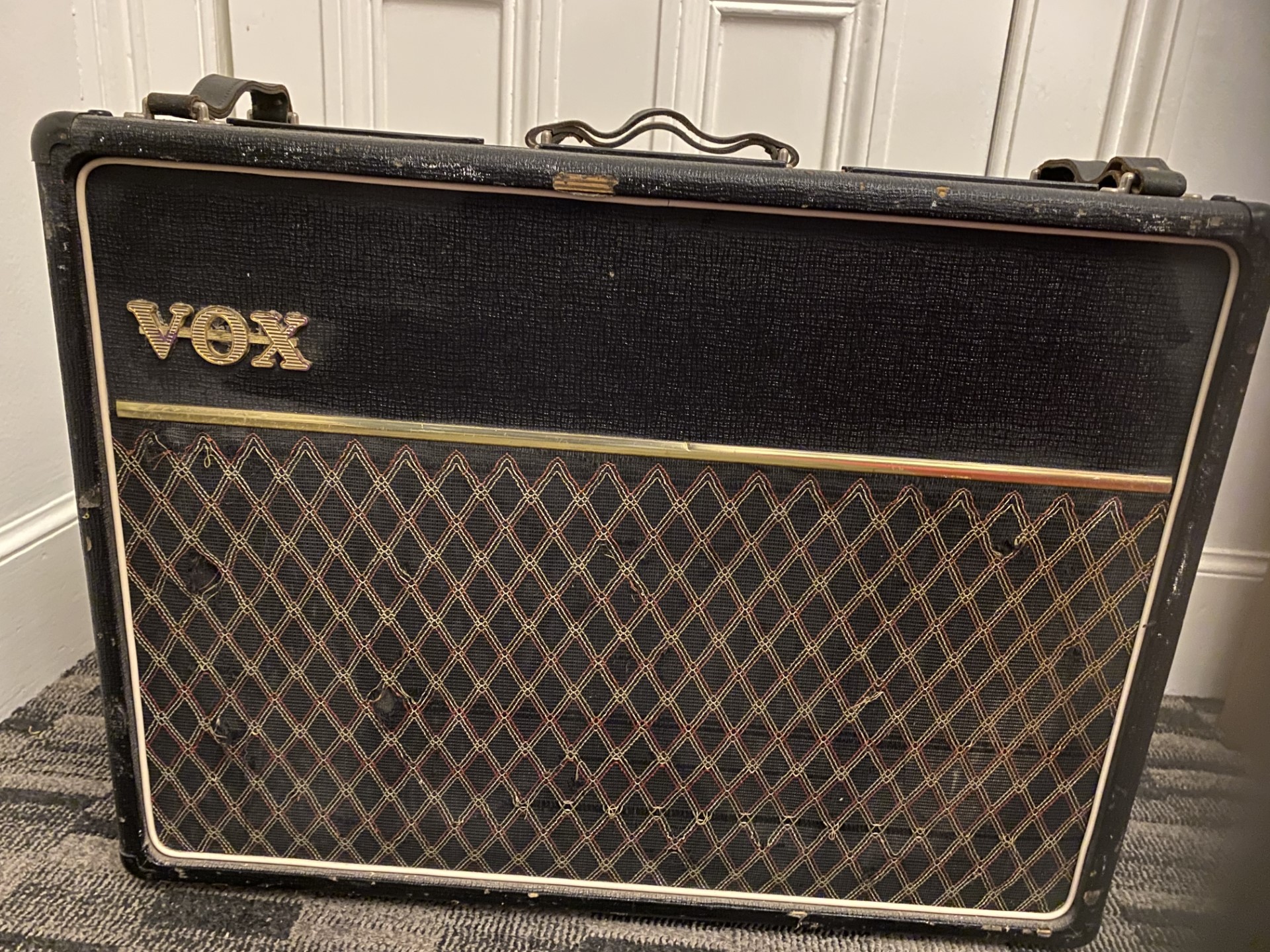
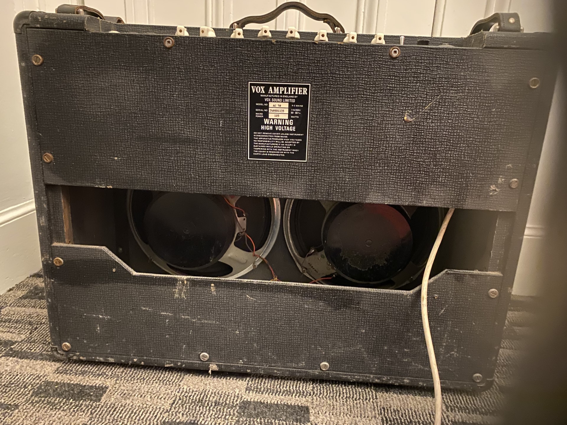
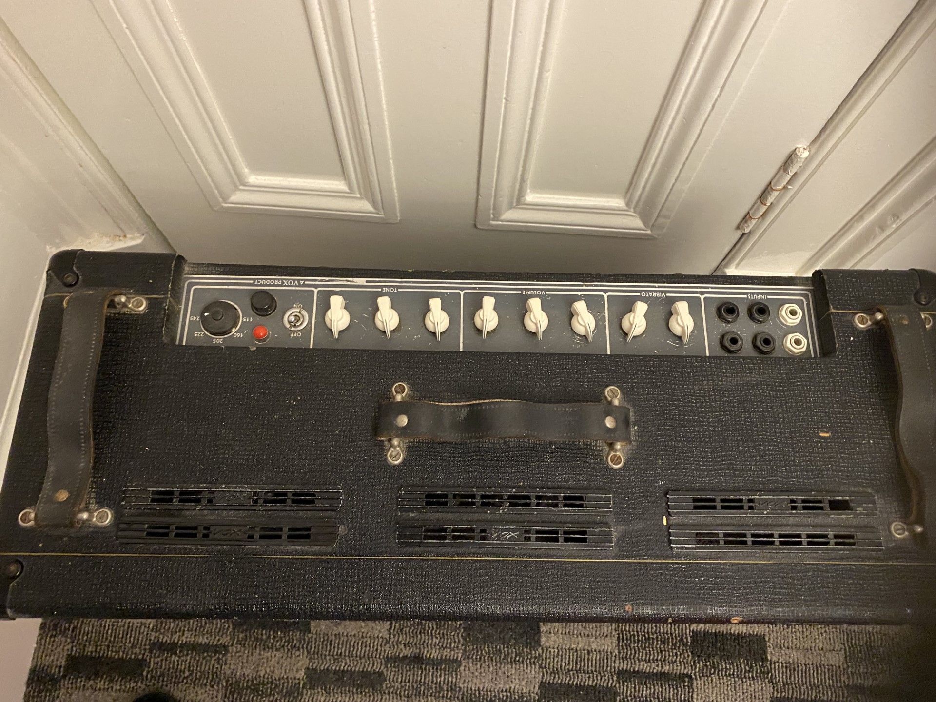
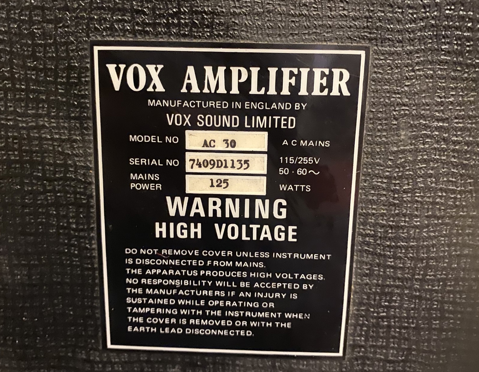
"Dallas Musical Limited" AC30 serial number 7409D1135.
25th March
Notes on the main external dimensions of the TV Front AC30. These are given in inches and fractions of inches:
CABINET
Main body of case: 21 1/2" tall x 21 3/4" wide x 10 3/8" deep.
Sides, top, and bottom: 5/16" thick.
Front surround: 3/8" thick; sides and bottom at front: 1 3/4" wide; top at front: 2 1/2 wide.
Control panel cut-out: 16 1/2" x 2 5/8", 1 1/2" from back edge of case.
Handle (dimensions taken from rear of case): centres of mounting hole pairs: 1 3/4" apart, 5" from rear edge of amp; leftmost hole is 6 5/8" from side; right-most hole is 8 3/16" from other side.
Underside of the top of the cabinet showing the battens beneath the control panel cut-out and the off-set fixings of the handle.
BAFFLE
Main dimensions: 18 1/4" tall x 18 3/4" wide x 3/4" thick.
Speaker cut-out: 10 5/16" diameter, 1 1/4" from bottom of baffle.
Vent: 12 7/8" long x 5/16" tall, centred, 3 1/2" from top of baffle.
BACK BOARD
Main dimensions: 19 5/8" tall x 19 3/4" wide x 1/8" thick.
24th March
Single speaker TV Front AC30 serial number 4158, probably late autumn / early winter 1960, close to the end of the model's run. Some early TV Front AC30 Twins may have have made their first appearance in the high 4100s, but no genuine example is known at present.
At some point before the late 1980s, the original diamond-pattern rexine of 4158 was painted over and the handle mounts and one face of the slider board done in a fetching day-glo orange. The other side of the board still has its original black (and can be flipped around if need be). The cabinet will be left as is and not "put back to stock".
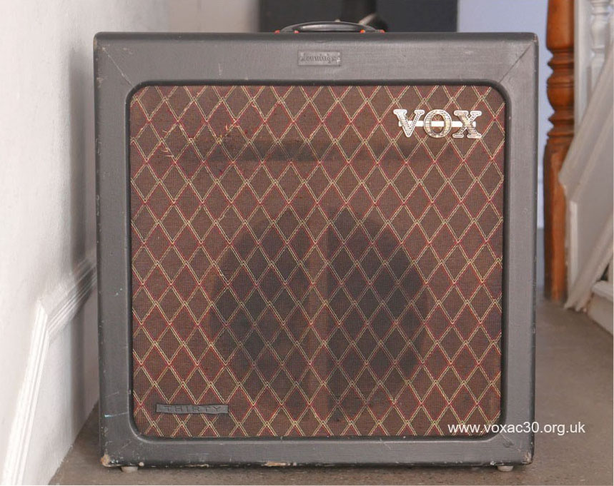
The tops of the Bulgin knobs fitted to the amp in the 1970s/1980s can just be seen in the pic. above. These have now been removed and cream Bulgin pointer knobs put in place for the time being.
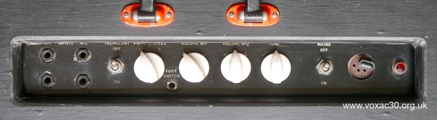
Control panel. The Bulgin "cooker" knobs are not original to the amp.
Details on the electronics to be posted in due course.
21st March
Below, two forms of the information panel of OS/030 for the Vox Continental organ, the first the version embodied in the Thomas Organ service manual (and widely circulated on the web); the other the JMI sheet, with original sheet number in place.
It is not known why the Thomas Organ sheet (along with others for the Continental) has its OS number blanked out then later supplied by hand.
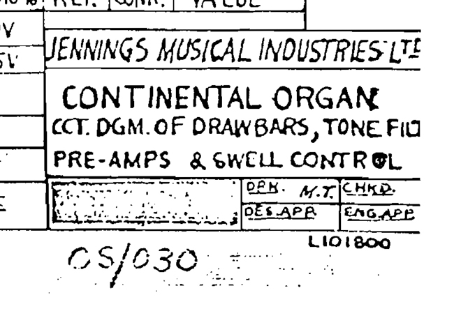
Detail of OS/030, Thomas Organ service manual.
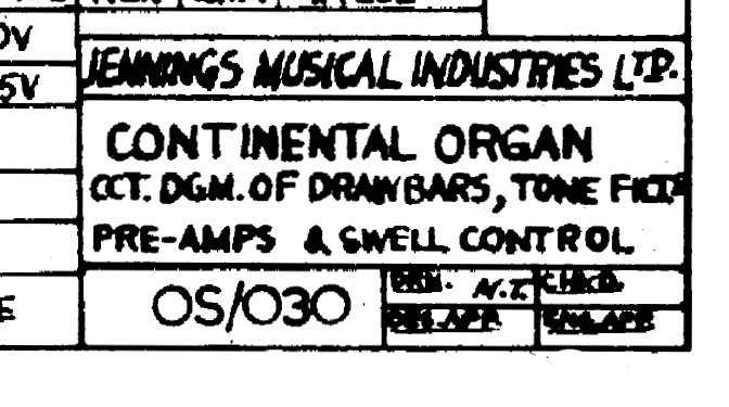
Detail of OS/030, JMI sheet, circulated principally in the UK.
18th March (2)
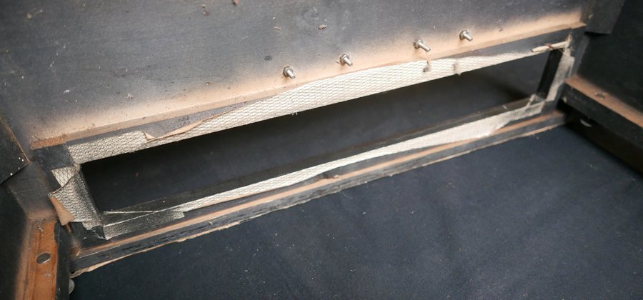
A note on a late single-speaker AC30 cabinet (autumn / early winter 1960). This originally had a removable batten to provide further support to the back board (made of pressed cardboard and therefore relatively flimsy). The screw hole that aligned with the batten is indicated in the picture below.
The batten slotted over two screws inset in the runners on the left and right hand side of the cabinet. Precisely what form it took is unknown - probably a straight piece of 1/2" x 1/2" timber (the runners are this size) with a block added on its front to align with the inner face of the back board.
The batten naturally had to be removable to allow the speaker to be fitted and removed. So far no other instance of the arrangement has come to light.

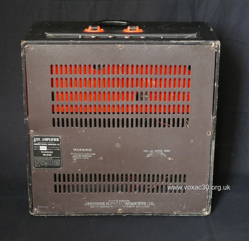
Pressed cardboard back board, the centre fixing designed to align with the removable batten inside the cab.
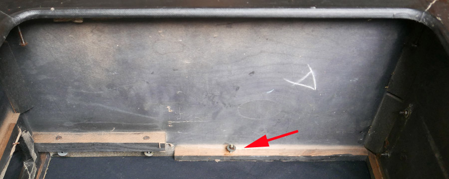
A view of one side of the cabinet, baffle removed, looking through the front. Left is top, with fixing points for the preamp slider board; right is the foot of the cab with fixings for the power section of the amplifier.
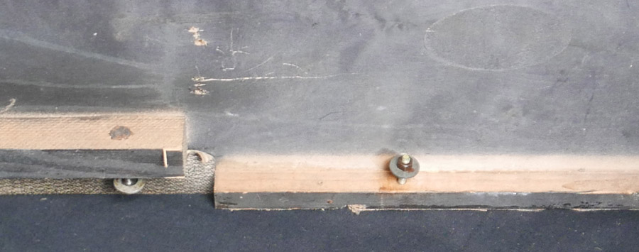
Detail of the shot above. The length of the screw indicates that the piece of timber is unlikely to have been more than 1/2" thick at the fixing point.
18th March
A small but significant change to the assembly of organs in 1958: the move from multi-core cables to single core wire for internal connections in the larger organs (the Model G in particular). This had two main benefits - versatility and material cost. However, there was one drawback. Single core wire tended to break more readily when an organ was moved.
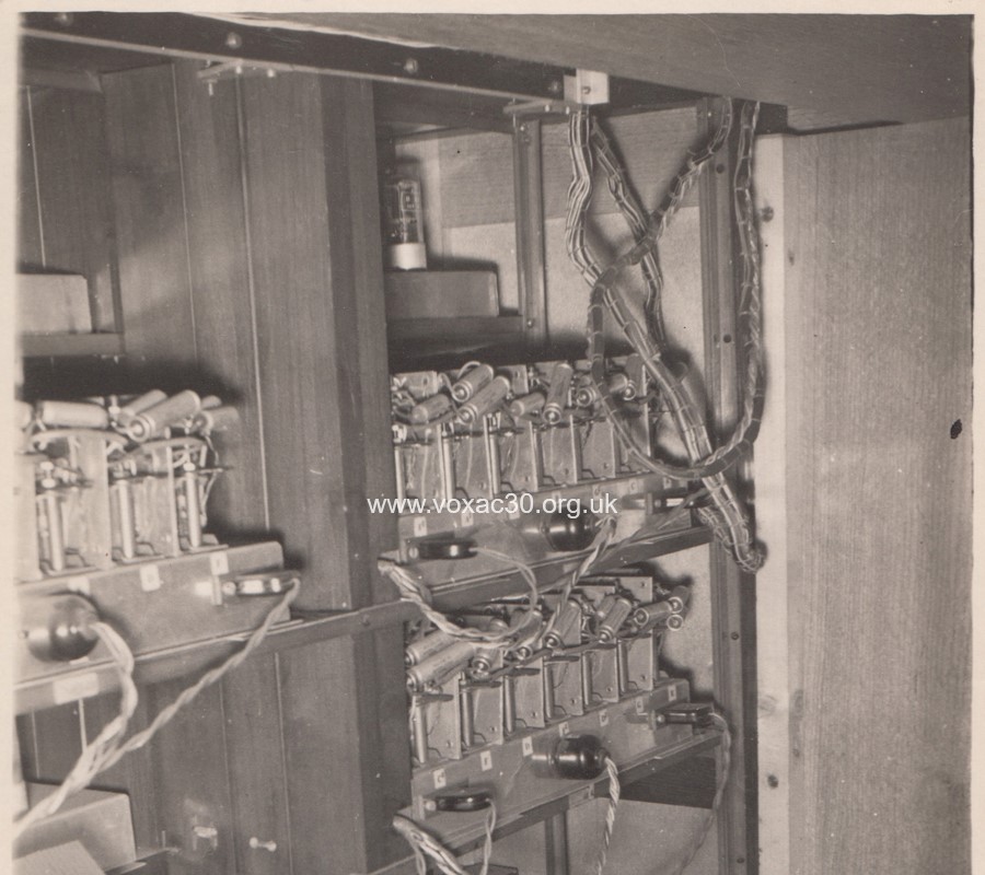
Interior of a Jennings organ - probably a Model G - photographed late 1957 / early 1958: twisted power cables, and loomed multi-core and single core.
17th March
Assembly of organs at Dartford Road, c. 1958 to 1960. The cable forms, voicing assembly sound generators, amplifiers and power supplies, were put together by three ladies: Sheila, Janice and Celia. Once complete, the assemblies were then soak tested for 24 hours at one end of the shed.
When the time came for the build, Charlie, the department's woodworker, would make frames and sort out any difficulties that arose in the cabinets produced for JMI by its external contractor (possibly Glock in Crayford). Dave Grant and Len Player then tackled final assembly (which would normally take a couple of days), mounting the various elements in the cabinet, wiring up the sections, and testing the organ's functionality - voicings, tuning, and so on.
The length of time required to complete an organ - start to finish - naturally varied according to the model of organ in view. Smaller ones took around six to eight weeks - "lead time" from the point at which the order came in. Larger ones, the Model G in particular, which required sets of ancillary speaker cabinets, could take as much as three months.
Thanks to Len for the details. Below, a picture taken in the organ section at Dartford Road, probably in 1957, a year before Len joined the company - the key contact assembly of a Model B "Entertainment" organ.

Detail of a Jennings Model B organ during assembly, late 1957 / early 1958. Photo: Toni Standing, Derek Underdown's daughter.
16th March
Thanks to Len, some info on the speakers normally provided with the Model G organ in the late 1950s - Len was responsible for the final assembly of the organs - across the Jennings range - at Dartford Road from 1959 into 1960, having joined the department in 1958.

Detail from the Model G brochure, c. 1958.
The bass speaker cabinet was around 6 feet tall, 4 feet wide, and 2 feet deep. Inside, there was a centre partition. The bass driver was positioned at the top of enclosure facing downwards, driving the sound to the foot of the cabinet and out through ports.
The wedge-shaped enclosures were normally fitted with a 12" Rola Celestion. Four such cabinets were conventionally installed with the Model G.
The diamond-shaped enclosures contained an 8" oval speaker - principally for reproduction of the trumpet militaire. Four such units were normally installed with the Model G, though as many as eight were sometimes provided.
In large churches, a colossal amount of wiring will have been needed to link the speaker arrays to the organ's power amplifier.
More to come (thanks to Len) on the assembly of organs at Dartford Road, c. 1958 to 1961.
15th March
Just to record the addition of two new entries to the list of known circuit diagrams for the Vox Continental organ: OOS/036 - an analogue of OS/030 (Drawbars and Filters); and TO/037 - capacitor values for generator octaves.
14th March (2)
Thanks to Joanna, shots of an AC30 formerly belonging to Tony McPhee of "The Groundhogs" - cabinet, with serial number 12806N, recovered and regrilled; the chassis, copper panel with integrated Top Boost controls.


14th March
Below, a quick shot of the JMI "Dealer's Servicing Diagram" for the Continental dual manual organ, designated TMO/015, drawn by R. A. Lester probably in the first half of 1966, though no date is given in the information panel. The sheet measures 15 1/2" x 11 3/4" (much as the one prepared for the single manual, illustrated in yesterday's entry).
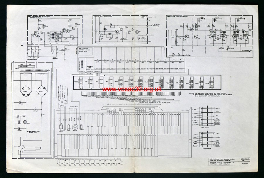
TMO/015.
As one might expect, a copy of TMO/007 was subsequently sent to Thomas Organ in the USA. A version is encapsulated in the large Thomas sheet for V303J ("J" standing for Jennings), along with OS/095 for the walking bass circuit (indicated in purple), and TMO/007 for the internal controls (indicated in green).

Thomas Organ fold-out block diagram for the dual manual Vox Continental organ. The sheet is a composite of JMI TMO/015, TMO/007, and OS/095.
At present, five "TMO" diagrams are known to survive: 002, 007, 015, 030, and 071. Following the collapse of "Vox Sound Equipment Limited" (in December 1969), a good deal of material, old and new, was simply thrown out.
In relation to circuit diagrams in general, one question that arises is the extent to which Thomas circulated the sheets (sent by JMI) within the USA prior to the creation of the service manuals in late 1966. JMI evidently began sending relevant batches of documentation in late 1964 and early 1965 - to accompany the amplifiers, organs, and guitars exported to the States following the public announcement of the "Million Dollar Deal". Little evidence has emerged so far to show that Thomas did much, if anything, to distribute the diagrams early on.
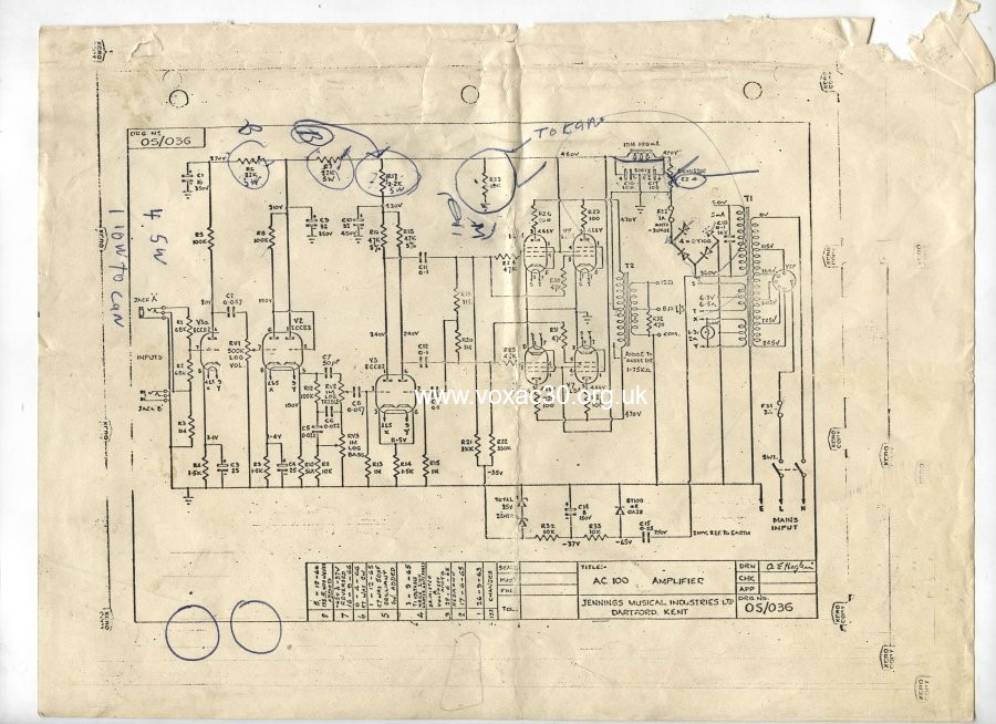
Below, a rare instance of the supply of a single sheet: a copy of OS/036 for the AC100, xeroxed several times, sent out by Thomas Organ to some former owner of an AC100 with a serial number in the 500s. The last date in the information panel is December 1966. This is not the version of OS/036 embodied in the Thomas service manuals.
JMI by contrast regularly sent out sheets in the UK throughout the 1960s - sometimes singly, sometimes in folders. That nothing similar happened - or seems to have happened - in the USA from early 1965 to late 1966 may simply be a result of the newness of the equipment. Perhaps somewhere in the USA, though, there are collections of diagrams that were sent out early on by Thomas from Sepulveda or Evanston - those of course quite distinct from collections of original JMI diagrams obtained from the UK by Vox aficionados in the USA in the 1980s and 1990s.
13th March
The JMI "Dealers Servicing Diagram", a fairly detailed "block diagram" for the single manual Continental drawn by R.A. Lester in July 1966, designated TO/065. The sheet measures 15 1/2" x 11 3/4". It was designed for use with the "Theory of Operation" booklet.

TO/065 - block diagram of the single manual Contintental organ for dealers.

TO/065, panel.
The blocks (also referenced in the booklet) are: 6500 = generator boards; 7100 = vibrato; 7200 = preamp; 7300A = power supply; 7400 = keyboard contact assembly. The booklet adds 7700 for the dual manual's "walking bass". The dealers servicing diagram for the dual manual Continental will be posted soon.

Front cover and first page of the booklet.
Block diagrams were a standard means at Jennings (as for other organ makers) of giving an overview of the relationship of elements. Below, a sheet drawn by Derek Underdown, c. 1957, for the Jennings Organ Company's "V" series organs.

Block diagram drawn by Derek Underdown for the "V" series organs, c. 1957.
12th March
The material on Vox Continental circuit diagrams posted below over the past few days has now been collected on a page of its own - available here - and augmented with a list of known sheets (which is bound to grow). The hope is to provide full copies of the twenty or so diagrams listed, along with the various service booklets.
11th March
A little more on JMI's updating of its service data for the Continental organ range in late 1965 and early 1966. The principal draughtsman of the new sheets was R.A. Lester, who appears to have worked exclusively for the Organ Dept, at the West Street Works in Erith. Albert Hogben did more or less everything else at this time.
Lester's office initially will have been on the top floor of the Works, where final assembly of the Continentals took place. After the fire of December 1965, he is likely to have moved back to Dartford Road.
Below, the new version of the diagram for the Continental's Vibrato Board, OS/124, and the corresponding layout sheet, TO/052.

OS/124, drawn on 27th March, 1966, referencing TO/052.

TO/052, dated 10th October 1965. This replaced OS/029 of early 1963.
Just to add that by July 1966, the "TO" series had reached sheet number 65, a "Dealers Servicing Diagram" for the single Continental Organ, the latest that has so far come to light. With the advent of the Riviera in 1967, the sequence seems to have come to an end. Layout sheets for the newcomer are prefixed "TRA" and "TRC".
10th March (2)
Some preliminary notes on JMI layout sheet TO49 for the tone generator board of the Continental organ. The copy illustrated below, dated November 1965, is likely to have been drawn up to accompany the release of the Super Continental dual manual.

The sheet measures 13" x 8". OS/030 provides the key to the component values, given in TO/049 simply as "R1" and "C5", and so on. The red shapes are the PCB traces. A larger copy of TO/049 will be made available shortly.
That sheets such as these existed in 1964 is clear from OS/064, a block diagram for the single manual Continental, dated November of that year:

Detail of OS/064, drawn by Albert Hogben in late November 1964, referencing TO/049 and OS/027.
Quite when JMI kicked off its "TO" series of diagrams is unknown at present - 1964 certainly, possibly even late 1963, when production of the single manual Continental had reached a more settled point (in relative terms at any rate).
Although copies of both OS/064 and TO/049 were sent to Thomas Organ (presumably in connexion with the "Million Dollar Deal" of late 1964), Thomas does not seem to have explicitly referenced or illustrated the sheets in its service literature until early 1967. As mentioned a couple of days ago, the main service aid up to that point was the "Pocket Reference Guide of Replacement Parts", its photographs providing the principal means of helping the owner / service repairman identify and order the requisite replacement board or boards.

Thomas Organ, "Pocket Reference Guide of Replacement Parts", 1966. But for the omission of two capacitors at left, the board pictured is laid out in accordance with TO/049.
Below, the generator board for "B" in Continental TC1888, its arrangement (though not component types) corresponding to the picture inset above. Organs with TC serial numbers in the 1500s, however, have an entirely different type of board; and for organs with TC numbers in the 1200s and lower there is yet another (one at the very least).

Detail from Continental TC1888.
Repairmen in England in 1963 and 1964 needed to be as much on their mettle when it came to these boards as Thomas repairmen had to be in the later 1960s. Parts from various production runs were often not interchangeable.
Clearly such things were known to Jennings. When discussions surrounding the move to the West Street Works began in Spring 1964, one of the hopes must have to been improve the consistency of production. So far as one can tell, the assembly of organs - transferred from Dartford Road - was in full swing there by early 1965.
10th March
Below, details (for the time being) of three original circuit diagrams for amplifiers in the Domino range: OS/026 for the Domino Super Reverb Twin; OS/037 for the Domino Reverb combo; and OS/051 (first version) for the AC4 and Domino Normal. The sheets measure 10" x 8" and came as part of a set of around forty-five Jennings diagrams put together in all likelihood for the company's service engineers. Rodney Angell, JMI's R&D engineer from 1965 through to Spring 1968, had a near-identical set.
The sheets will be posted in their entirety shortly - a new Domino circuit diagrams page. The main Domino amplifiers index page can be found here.
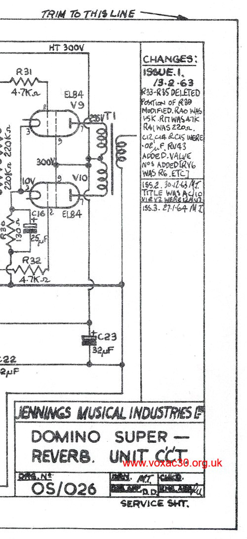
A detail from OS/026, originally drawn up for the Vox AC10 SRT in February 1963, but not used for the model until late 1964. In the meantime, the circuit was adopted for the Domino Super Reverb Twin - as Mike Turner's note (ISSUE 2) indicates, certainly by late December 1963. General notes on the four versions of OS/026 are on this page.

Information panel of OS/037 for the Domino Reverb combo, the sheet dated 7th October, 1963.

Information panel of the first version of the circuit for the Domino Normal combo amplifier (shared with the AC4), sheet dated 6th March, 1964.
9th March (2)
Thanks to Andy, pictures of AC30 serial number 1255, produced in the Birch Stolec factory, final assembly in late 1972. In company with serial number 1264 (below, entry for 7th March), reverb was envisaged but not implemented.
Further pics of serial number 1255 can be found here.

9th March
A Jennings service folder for the Vox Continental organ, probably from early 1966. The name on the front is that of Ken McDonnell, Jennings Organ Production Manager from early days (at least as far back as 1956). The person who made the notes presumably jotted them down while on the phone to the Service Department at Erith - "McDonnell" is given, at second attempt, as "McDonnall".
The folder contains a number of sheets that are scarce these days - four "TO" layouts (part in colour), and a series of diagrams produced by JMI in early 1965 and early 1966 for the Super Continental (two manual).
Also encompassed is a 10" x 8" booklet issued by JMI on the "Theory of Operation". Pictures of another copy were available on the web some years ago (can't recall where), but those seem to have disappeared.

The folder measures 13" x 8 1/2".

The JMI circuit diagrams and layout sheets contained in the folder.
Front cover and first page of the booklet.
8th March
Some notes coming on service manuals and circuit diagrams for Vox Continental organs. Below, the outer cover of the Thomas Organ manual from 1967. This superceded the handy "Pocket Reference Guide of Replacement Parts" issued by Thomas in 1966, the main point of which, as far as organs were concerned, was to illustrate the differences between the tone generator boards installed in the three main types of single manual Continental: the V301J (Jennings, produced at Erith) and the V301E and V301H (produced in Italy), along with the V304 (Jaguar). Notes were also provided on the double manual Continentals: the V303J (Jennings, produced at Erith) and the V303E (made in Italy).
In the UK and Europe of course the Continental was known simply the "Continental", and the double manual as the "Super Continental". "V" numbers were only used by Thomas.
Also to add that through to the autumn of 1965 (when the "Super Continental" was brought to market), Jennings was sole manufacturer. EKO did not start producing its versions until later in the year, probably not in volume until early 1966.
By one of those strange quirks, the Thomas manuals of 1967 (and later) preserve a type of Jennings circuit diagram - a "TO" ("Transistor Organ") sheet - that is now extremely scarce in English sources. There were at one time around 50 different "TO" sheets, for the most part illustrating component layouts of boards and assemblies. The Thomas manual of 1966 to some extent copied Jennings in this respect (as one might expect), but with photographs rather than drawings - a much better way of doing things.

Thomas Organ "Vox Organs and Accessories" service manual cover, 1967.
7th March
Thanks to Sebastian, pictures of AC30 serial number 1264, "Vox Sound Limited", assembled at the Birch Stolec factory in late 1972, still in superb condition. The amp was evidently prepared as an AC30TBR, but the reverb tank never installed.
The main page on Birch Stolec AC30s can be found here.


The Celestion T2056 has the date code "KE27" = 27th October 1972.
6th March
Thanks to Piers, there is now a page of photos devoted to single speaker AC10 serial number 4619, early 1965, close to the end of the run.


AC10 serial number 4619.
5th March
Thanks to Thomas, pictures of AC30 Super Twin (amplifier section) serial number 3300B have been added here. The latest date codes spotted so far are on the TCC capacitors - "VF" = June 1964. As the speaker cabinet no longer survives, the date of final assembly (the first step towards the amp's being made ready for sale) is not certain - probably the last third or quarter of 1964 though. Speakers generally have/had later date codes than chassis.


AC30 Super Twin amplifier section serial number 3300B.
Coming shortly, pictures of a late Birch-Stolec AC30 (late 1972) and of a late single-speaker AC10 (early 1965). Both amps in superb condition.
Updates for November and December 2023.
Updates for June and July 2023.
Updates for March to May 2023.
Updates for October and November 2020.