
Vox AC30 website updates
September 2026
30th September
A note on the main octal socket on the 30 Watt Organ Amplifier. As one can see from the circuit diagram, the socket served two principal purposes: to bring the mains supply to the mains transformer; and to feed the amplified signal from the output transformer to the speakers.
Some care will have been needed when wiring the (octal) plug up, as the neutral and live lines of the mains transformer were both black, and the "live" and common of the output transformer both green.
Fortunately the pins of octal plugs are numbered to correspond with the numbered solder tags on the socket, but still, wiring up was not a job for the inattentive. Get one wire wrong, and no end of trouble might ensue.
It is likely that JMI had cableform diagrams setting out the detailed arrangement of both socket and plug. Note that reference is made on the sheet below to the "Power Cableform Diag." for the "Model G" organ.
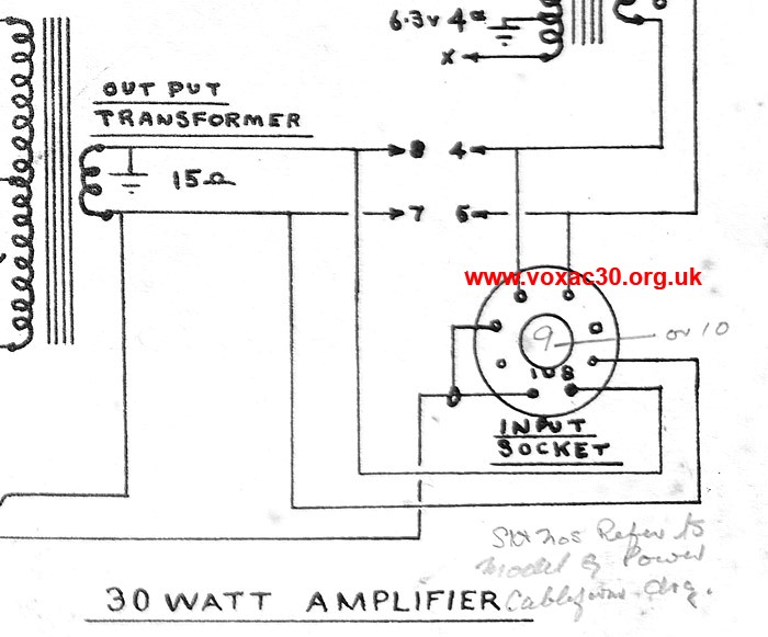
In contrast with the 50 Watt Organ Amplifier, the 30 Watt model had no voltage selector.
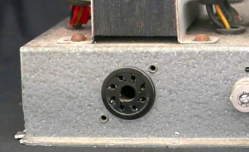
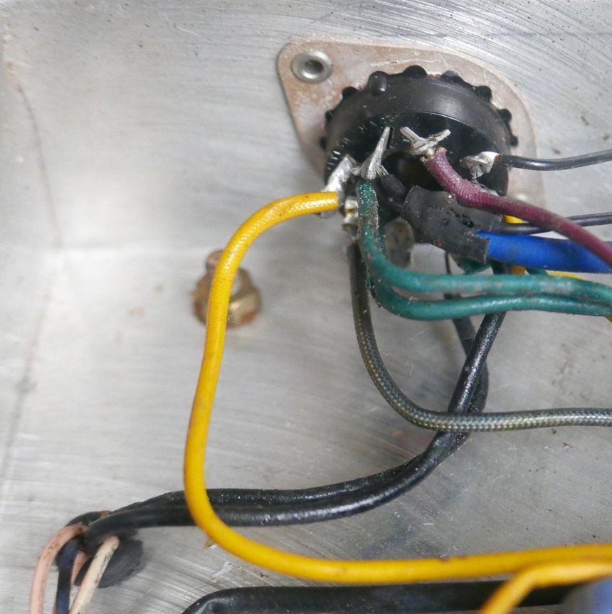
Live and neutral of the mains transformer (disappearing into the chassis pass-through hole) are both black. So for that matter is one of the earths, but that may belong to one of the windings of the secondary.
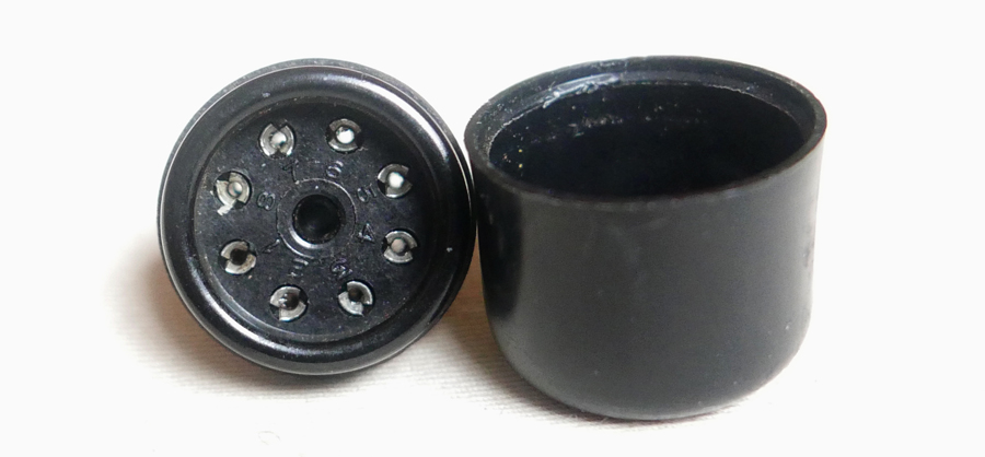
Octal plug with its top off. One can just make out the numbering of the pins on its base.
29th September
A quick shot of a VSEL/VSL sheet, ICC/011, for the preset panel cableform (cabling loom) of the Continental 300 and 301 organs. Where JMI is concerned, the term "cableform" goes back at least as far as 1956/1957 (large-scale sheets for the "Model G" organ).
Similar diagrams will have been produced (in late 1962 / early 1963) for early Continentals. Along with much else from that time, these have altogether disappeared from view.
The prefix "ICC" presumably references "Continental" and "cableform", but the significance of the "I" is unknown.
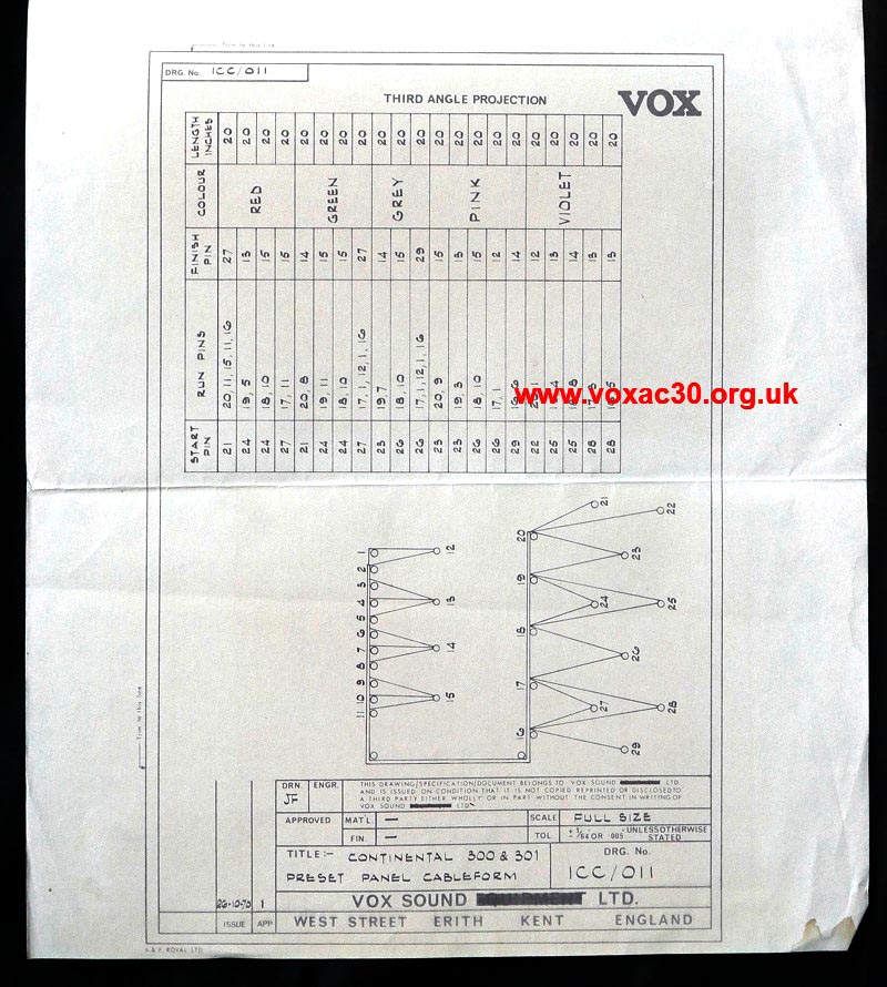
Sheet ICC/011, dated October 1970.
28th September
A new page has been started on the printed circuit boards developed by JMI for its Continental organs, mid 1964 to early 1968.
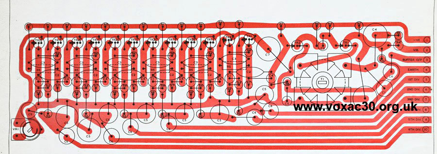
JMI component layout sheet TO/049, dated November 1965.
The page on Continental circuit diagrams will need some gentle updating to take account of material encompassed on the new page.
27th September
A provisional list of early JMI printed circuit boards for Vox transistor organs. It should be possible to fill the various gaps in the sequence (as it stands at present) in due course:
JMI 46 - Generator / Divider board (component layout drawn Nov. 1965).
JMI 47 - Vibrato board (component layout drawn Sept. 1965).
JMI 48 - Preamp board (component layout drawn Oct. 1965).
JMI 49 - Repeat Percussion board (revised version, 1965/1966), circuit published in "Electronic Organ Magazine", April 1969.
JMI 50 - currently unknown.
JMI 51 - Guitar Organ, Generator / Divider board.
JMI 52A-52E - Guitar Organ, voicing circuits.
JMI 53S - Vibrato Board, a revised version later 1966 (?), circuit published in "Electronic Organ Magazine", April 1969.
JMI 54 to JMI 59 - currently unknown.
JMI 60 - Guitar Organ, mother board.
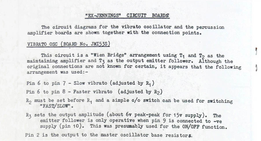
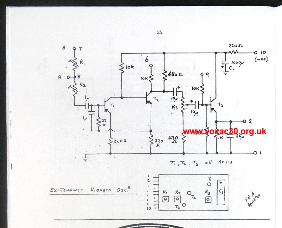
Below, the notes on JMI 53S - a revised Vibrato circuit board - published in "Electronic Organ Magazine", April 1969. The standard Vibrato board was JMI 47.
26th September
A detail of a photo taken by Derek Underdown in 1954 at 115 Dartford Road. The transformers appear to have Partridge labels (certainly not Haddon) as on the Power Pack illustrated in the entry below for 21st September. It may be possible to get a better image in due course.
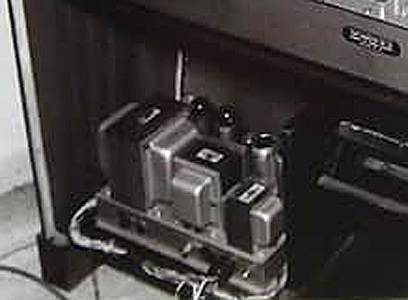
Also to note that the "TESTED" stamp on the underside of the Power Pack reads "ORECO", as on the Power Pack of a Jennings "Model C" organ that survives intact.
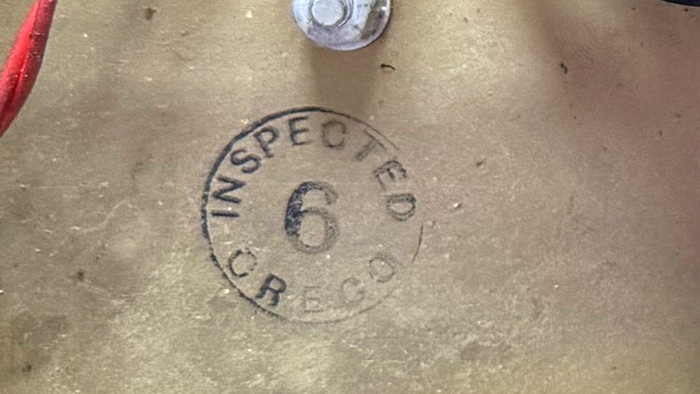
Detail of the Power Pack in an intact Jennings "Model C" organ. Thanks to Steve for the picture.
25th September
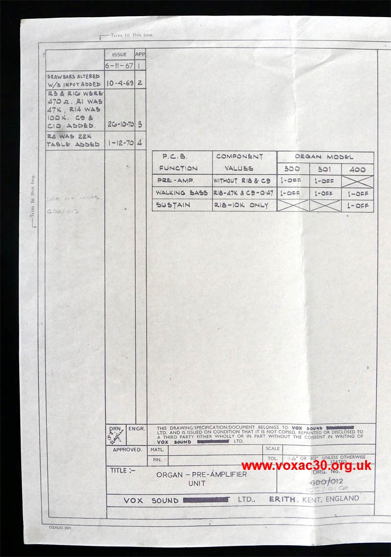
Jumping forward in time, a detail from a diagram (GDO-012) for the preamp circuit of Riviera and Continental organs, devised by JMI in November 1967. The sheet as we have it was drawn out by "Vox Sound Eqipment Limited" in April 1969 though and updated by "Vox Sound Limited" in late 1970. "GDO" probably stands for something along the lines of "General Diagram Organs".
A copy of the whole will be made available in due course.
24th September (2)
Rear view of the Jennings "Model A" organ mentioned yesterday, the 30 Watt Amplifier to the left of the central well for the volume pedal, a Power Pack no. 1 or no. 2, with a heater supply transformer finished in blue hammerite similar to that used for early AC1/15 chassis, to the right. The labour in these organs was naturally the wiring up.
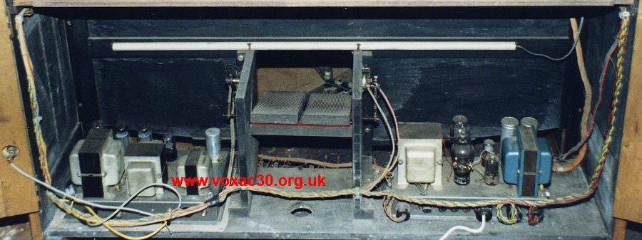
Thanks to Tony, detail from a photo taken in the late 1990s / early 2000s.
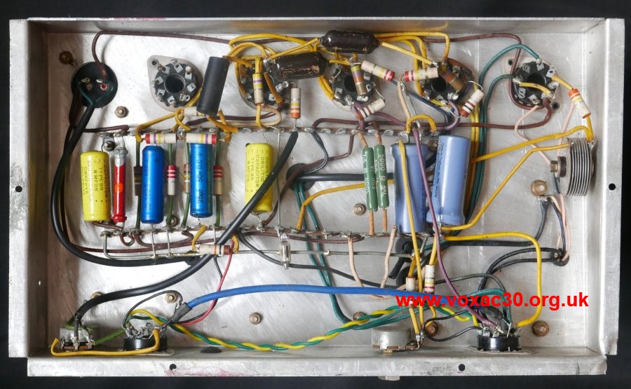
Some facts and figures: the chassis of the 30 Watt Amplifier was slightly larger than that of the Power Packs. It measured: 13 1/8" long; 7 3/4" wide; and 2" tall. Sockets were provided for five valves though the circuit required only four: a GZ32 rectifer, two EL34s, and a 6SN7. The vacant space (corresponding with the fifth socket) can be seen in the photo above. Compare with the shots of the 30 Watt Amplifier below.
The fifth valve socket is completely unwired. It is likely that chassis were prepared in this way to allow for the assembly of a 50 Watt Amplifier, which did require five valves.
24th September
Below, a Jennings 30 Watt Organ Amplifier, probably from c. 1955-1956, one of two currently known to survive (the other still in place in a "Model A" organ). Derek Underdown later used the circuit - his original design - as the basis for the power section of the single-speaker AC2/30.
He drew from both it and the 50 Watt Organ Amplifier too when he came to design the power section of the Vox AC50 in the latter part of 1963.
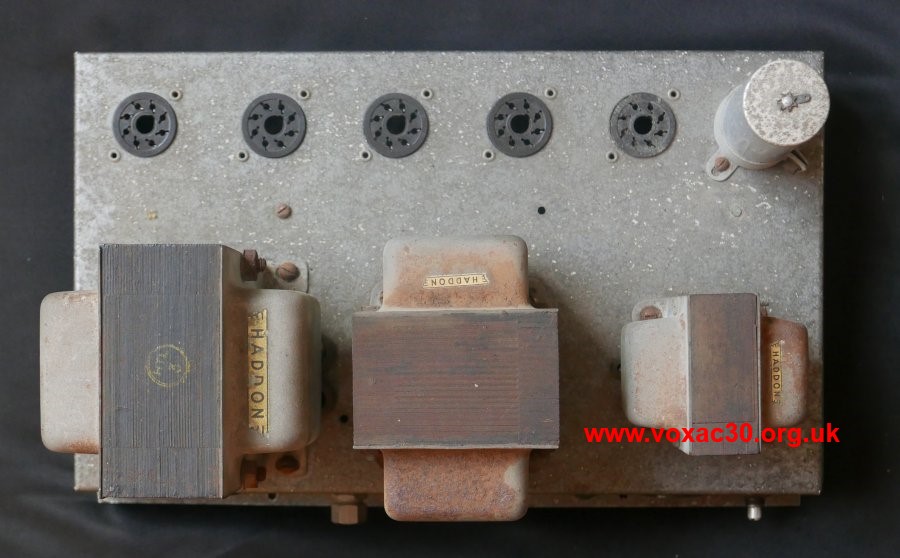
Left to right, Haddon mains and output transformers and choke. As in the case of the Jennings Organ Power Pack no. 3 illustrated a few days ago, valve sockets and other hardware are for the most part riveted onto the chassis plinth.
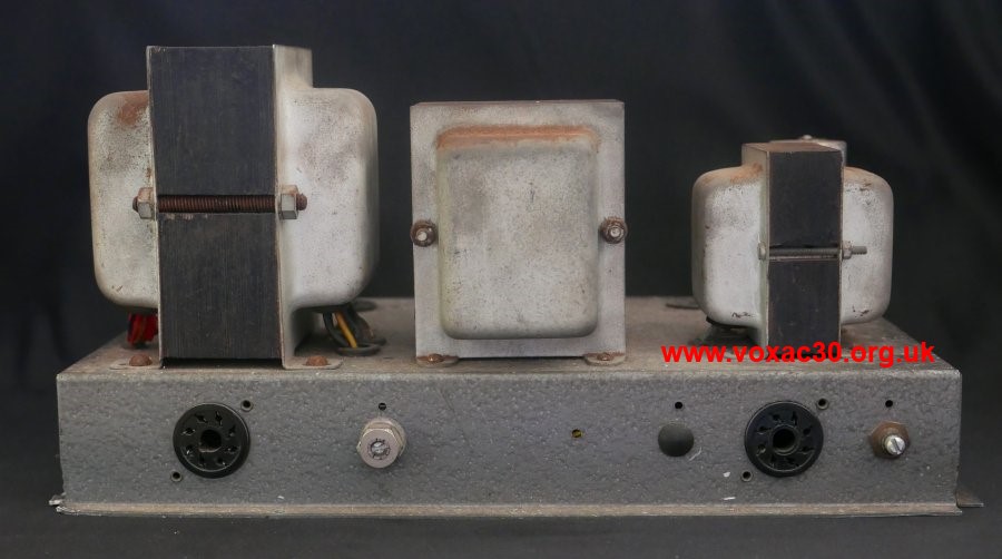
Sockets left to right: mains input and audio out (to speakers); bias adjustment; a blanked off hole (for another pot?); signal in and mains out; volume preset pot.
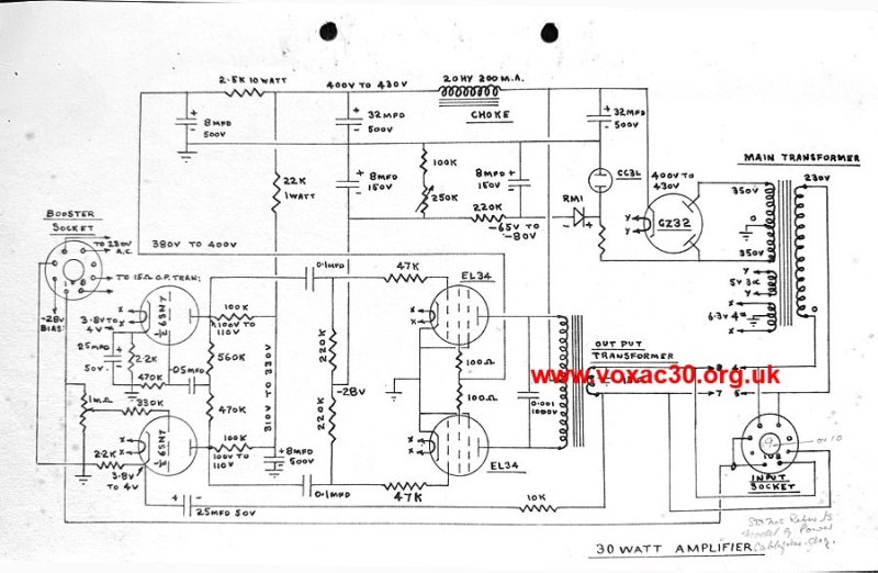
The circuit diagram (drawn by Derek) from a Jennings Organ Company Service Data handbook of 1958. Thanks to Steve for the image. The sheet is undated.
22nd September
The connections edge of the Jennings Power Pack chassis, left to right: mains power out; voltage selector; HT and main fuses; mains power in; 6.3v and 12v out; regulated HT voltages and 6.3v out.
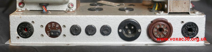
For those who like dimensions, the main chassis plinth measures 13 1/8" long x 6" wide x 2" tall. The flanges at base on three of the sides are 3/8" deep. The laminations of the mains transformer measure 5" x 4 1/4" x 2 7/8"; those of the low voltage transformer 4" x 3 7/8" x 1 3/8".
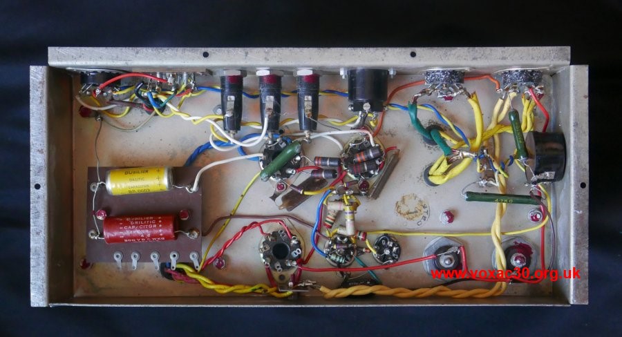
Hardware - valve sockets, octal sockets, and so on - is normally riveted onto the chassis rather than fixed by machine screws and nuts. Solder joints and fixings were checked and marked with red paint. The stamp on the underside of the chassis bears the legends "TESTED" "1" "ORECO" [not "ORGCO" as previously stated].
21st September
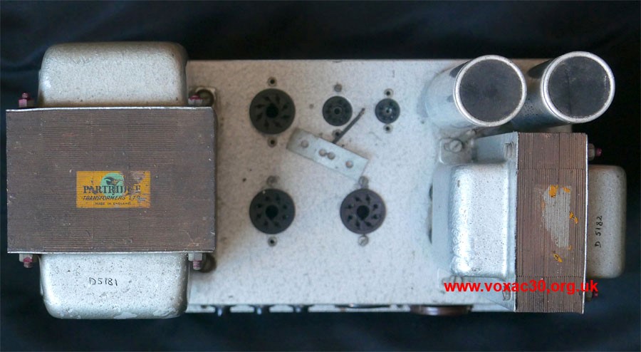
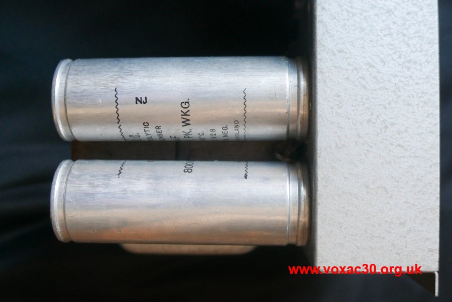
Further pics of the Jennings Organ Power Pack no. 3 that surfaced recently. The capacitors have the date code "NJ" = September 1956 for their manufacture. The two other Power Packs known to survive have Haddon transformers.
20th September
The page on a Power Pack and 50 Watt Organ Amplifier set that came to light in 2014 has been updated. More to follow.
19th September
Below, a slightly cropped shot of Derek Underdown's diagram for the "Power Pack no. 3", a surviving chassis pictured in yesterday's entry (probably from a colossal Model "G" organ). A fuller image of the sheet (showing the date of the modification noted lower left) will be posted in due course.
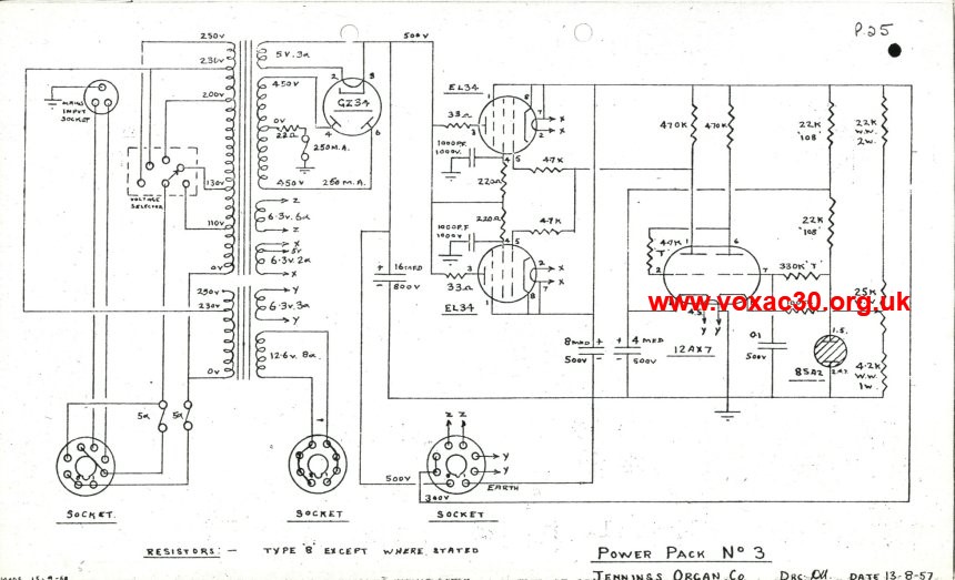
As has long been known, when Derek came to map the single-speaker "AC2/30" out for production, he borrowed a good deal from the organs he had designed, not only taking the circuit of the "30 Watt [Organ] Amplifier" as his starting point for its power section, but adopting the standard format of organ chassis as its basis - or rather base - too, fixed in the bottom of the cabinet.
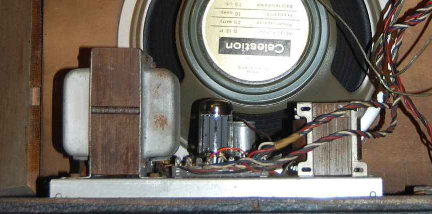
Power section of an AC/30 in the bottom of the cabinet.
18th September
Recently surfaced, a further 50 watt "Power Pack no. 3" from a Jennings organ, this one with Partridge rather than Haddon transformers. The circuit, designed by Derek Underdown, was drawn out clean in August 1957. More to follow shortly.
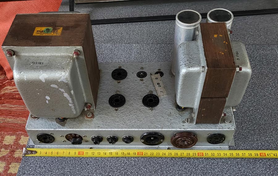
The mains transformer (450-0-450v with 5A and 6.3A windings) is part number "D5181"; the smaller transformer (6.3v and 12v windings) is "D5182".
16th September
A late Jennings Univox J7, split front, mid or later 1963, serial number in the 1300s. Some general shots of serial number 1329 can be found on the page on late examples of the J6.
Production of the J7 did not run much beyond the high 1300s, later 1963, if at all.
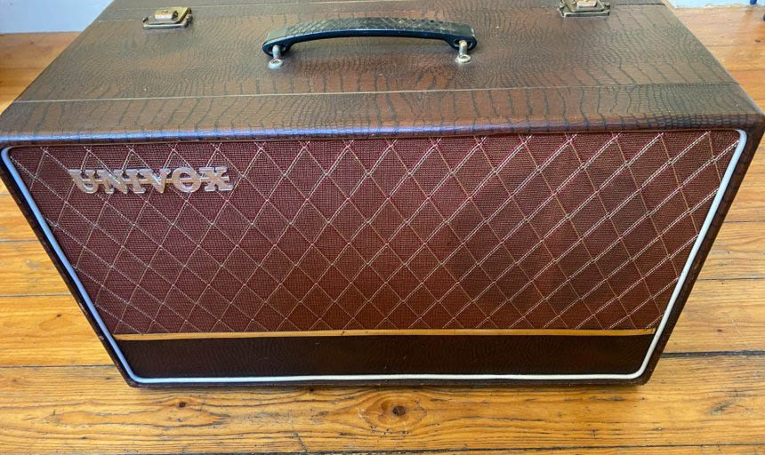
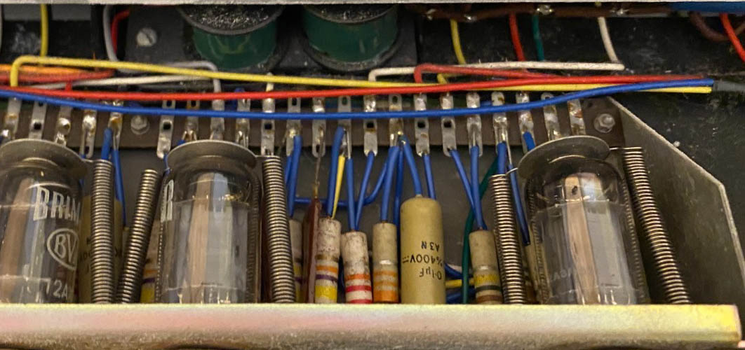
Mullard mustard cap. with date code "A3N" = first quarter of 1963; one of the Brimar valves with "2A3" = 2nd week of '63.
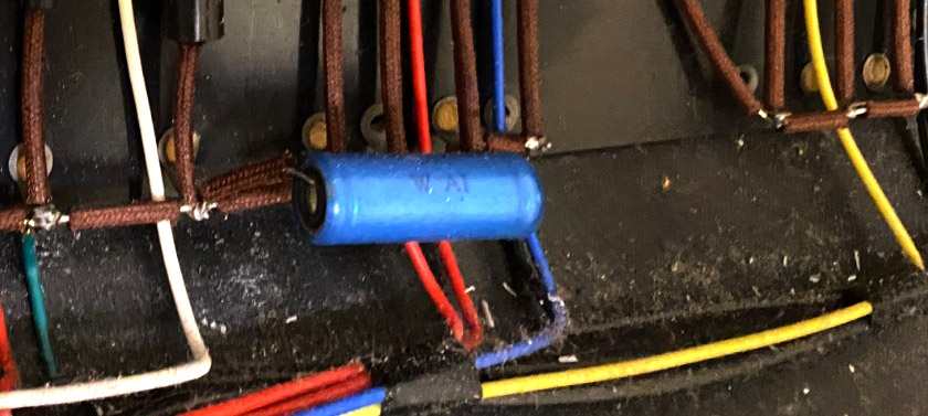
Hunts cap. with date code "WAI" = 19th week of 1963 for its manufacture.
15th September
The page on the Domino Bass, linked in yesterday's entry, has been expanded with further examples and images. One of the striking things about the sequence is not so much the varying cosmetic form adopted for the model in 1965, but the complete absence - so far - of amps with serial numbers in the 4000s. We jump from the 3900s straight into the 5000s. More to come on this gap in due course.
14th September
Some notes on the 12" Fane speakers in Domino Bass speaker cabinets:
1. - three identifiably different types were used during the course of production: 122/10; 122/12; and 122/14. All were 15 ohms, 20 watts handling, the principal difference being the strength of the magnets: 10000 gauss, 12000, and 14000.
2. - Fane supplied the first batches of speakers - probably 122/10s to judge by the depth of the magnet - with frames in Jennings blue, much as Celestion T530s. This dark blue was later dropped and speakers came to JMI finished in silver/grey or light blue hammerite.
3. - the Pulsonic cone code on one of the early blue Fanes is "48/102/006". The week number "48" has not turned up so far on cones made for the Celestion blue - there is a large gap between 42H1777 and 52H1777 in early 1964. "48" would seem to fit well at some point in late December 1963 / January '64 though. The overview of Pulsonic cones in Celestion blues and silvers can be found on this page.
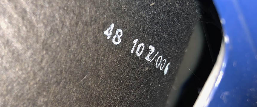
Detail of the speaker of Domino Bass serial number 1280. The chassis has components and valves with late 1963 date codes.
13th September
Thanks to Mark, pictures of AC30 Twin serial number 12980B. The speakers have Pulsonic cones with the code "4H1777", which indicates April or early May 1964 for their manufacture, the amp as a whole likely to have been ready for sale not too long after the speakers had been fitted, perhaps mid or late April.
Serial number 12867B has speakers dated 7th April '64, cone codes unknown at present.
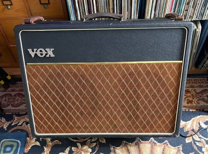
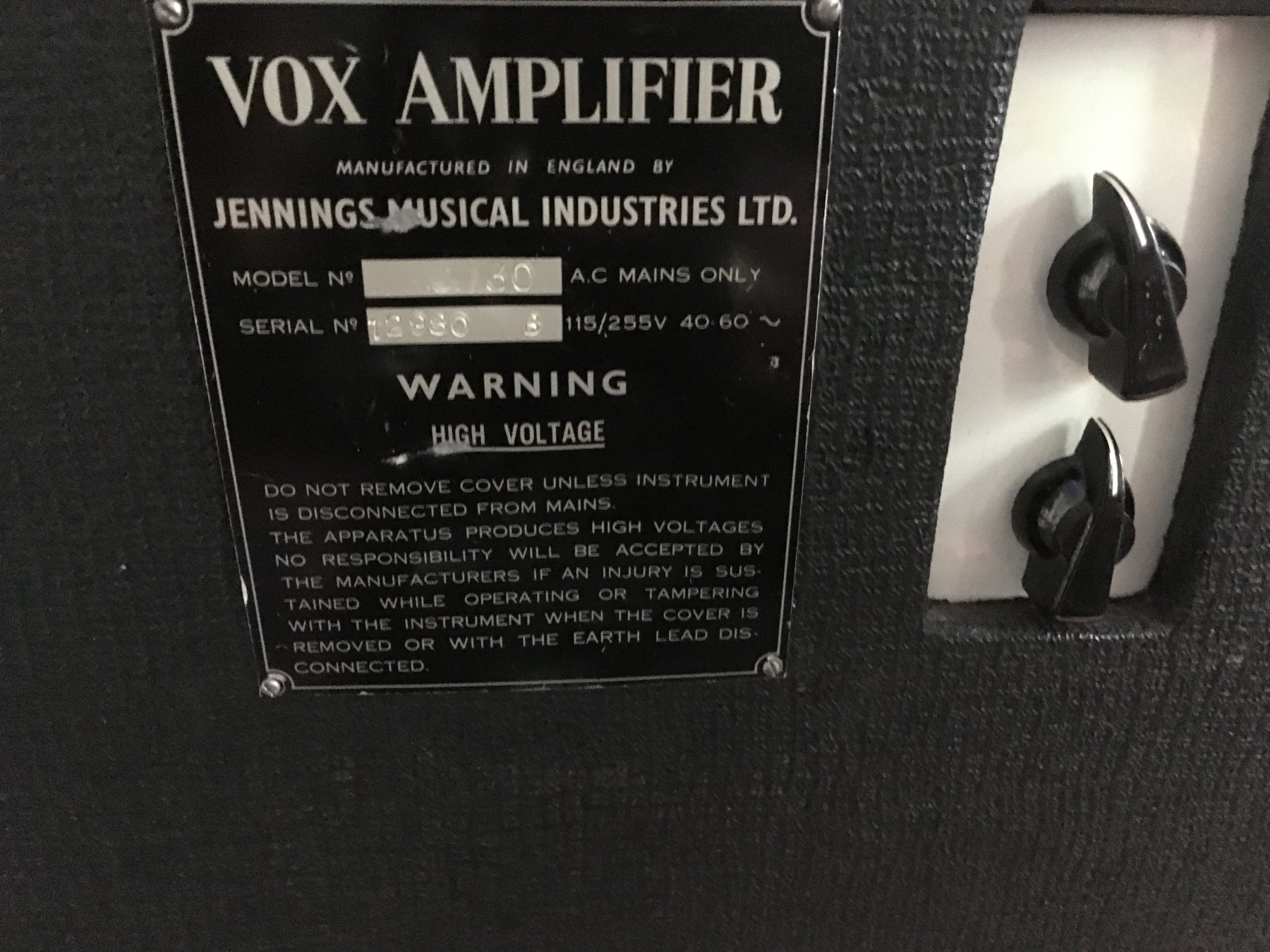
AC30 serial number 12980B. The Top Boost module is a later addition.
12th September
The list of circuit diagrams for the Riviera organs currently known to survive has been augmented with the six entries noted below. Details of GDO/012 to follow.
GDO/010 - Riviera 1 Walking Bass.
GDO/011 - Riviera 1 and 2 Vibrato.
GDO/012 - Riviera 1 and 2 drawbars and preamp, sheet begun in November 1967.
GDO/013 - Riviera 1 and 2 note generator.
GDO/014 - Riviera 2 100W transistor amp.
GDO/016 - Riviera 1 50W transistor amp.
11th September
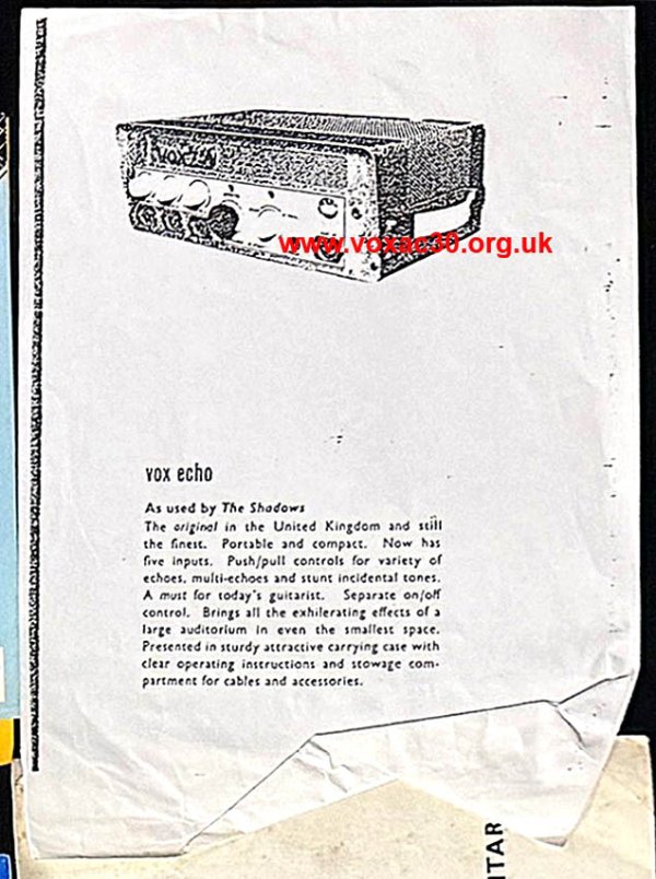
Recently at auction (part of a larger lot), a sheet photocopied from some JMI original, possibly the v. scarce catalogue of late 1962: the Vox Echo. The picture is an old one, out of kilter with the description, which gives the number of inputs as five - "Now has five inputs". The unit actually being offered is likely to have been a Meazzi PA304 - the "Stereo-Echomatic". The surviving Jennings circuit diagram for the Stereo Echomatic - OOS/034 - was for an earlier version though with three inputs.
10th September
June 1949, an advert from Tom's house magazine (sent out from 119 Dartford Road). As mentioned yesterday, W.S.E. accordion mics were certainly available direct from Jennings at least as far back as Spring 1948. Although it seems likely, on balance, that the majority of those requiring amplifiers in early days would be referred to Romilly Street, the possibility that Tom stocked a small number of units from time to time cannot be entirely ruled out.
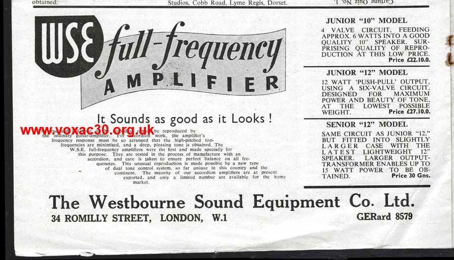
June 1949.
9th September
Spring 1949, Tom's stock totalling over 300 items. His premises at this time were 119 Dartford Road, where he lived, and the shed at back. 100 Charing Cross Road, and numbers 115 and 117 Dartford Road came later.
Accordions and accessories, harmonicas, and smaller instruments probably accounted for the bulk of his stock. Among the accessories, certainly the W.S.E. accordion microphone (advertised in spring 1948), and perhaps the W.S.E. "Junior Twelve" amplifier, listed in an advert, summer 1950. Whether he had guitars in spring 1949 is unknown at present. The first mention (and illustration) comes in the autumn of 1950.
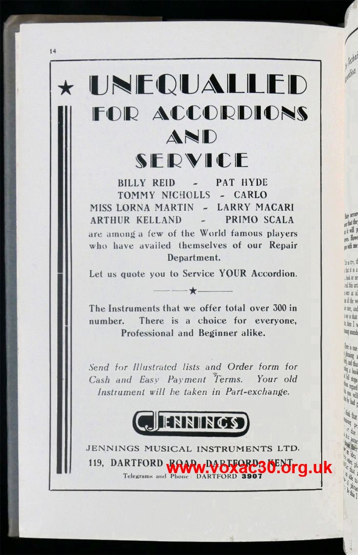
Spring 1949.
8th September
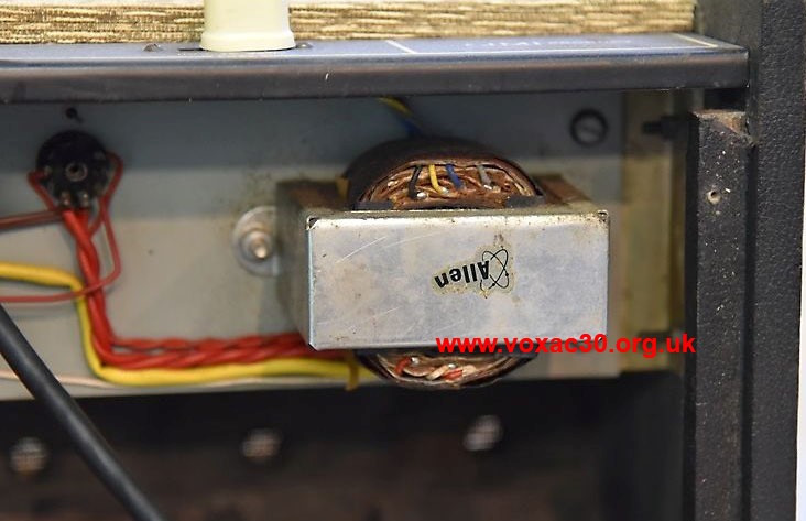
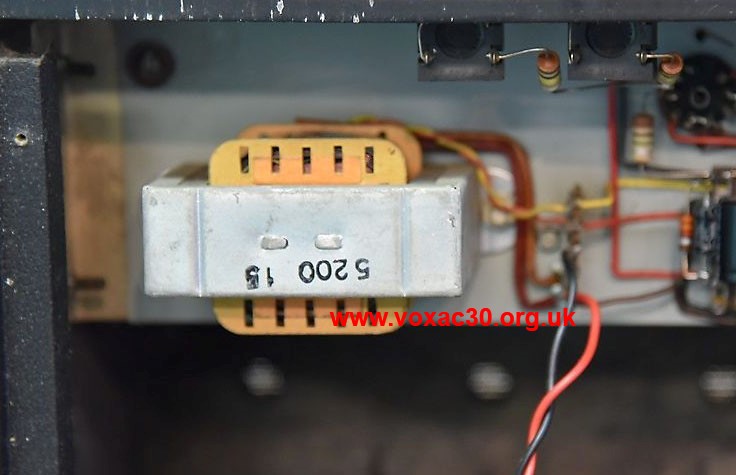
A couple of details of a late Domino Bass chassis assembled for JMI at some point in 1965 (probably mid) by Triumph Electronics in Purley: output transformer stamped "5200 15" (15 ohms), mains transformer made by Allen.
Allen transformers were also used later by Burndept for the JMI solid state "Traveller" amplifier.
Output transformers marked "5200" (made by Richard Allan) are standard in AC4s, which the Domino Bass effectively was in terms of electronics.
Just to say that the cabinet of this Domino Bass now bears the serial number plate of a Domino Reverb along with a note on yellow dymo tape to the effect that the amp had been consigned to Denis Peyton of the Dave Clark Five by JMI. Honestly, as if. The man (initials JH) who added the tape and probably the plate too evidently had some sort of abiding obsession with Peyton. Why is anyone's guess. If you see a guitar or amp purporting to have some connection with Peyton you can be sure that JH has been at work.
The Domino Bass chassis pictured below is perfectly ok though (ie no fiddle-dee-dee).
7th September
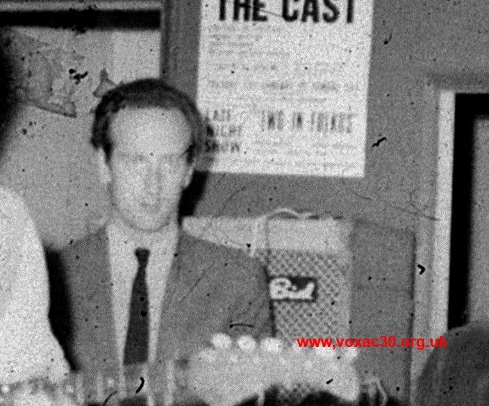
Pictured rehearsing in mid or later 1964, "The Black Sheep" with a Bird "Golden Eagle" amplifier (not a 30 Reverb as stated yesterday). Its cabinet was evidently divided into two main sections, a compartment for the reverb spring at foot and a larger compartment for the amplifier chassis and speaker. A further smaller compartment was provided for the mains cable.
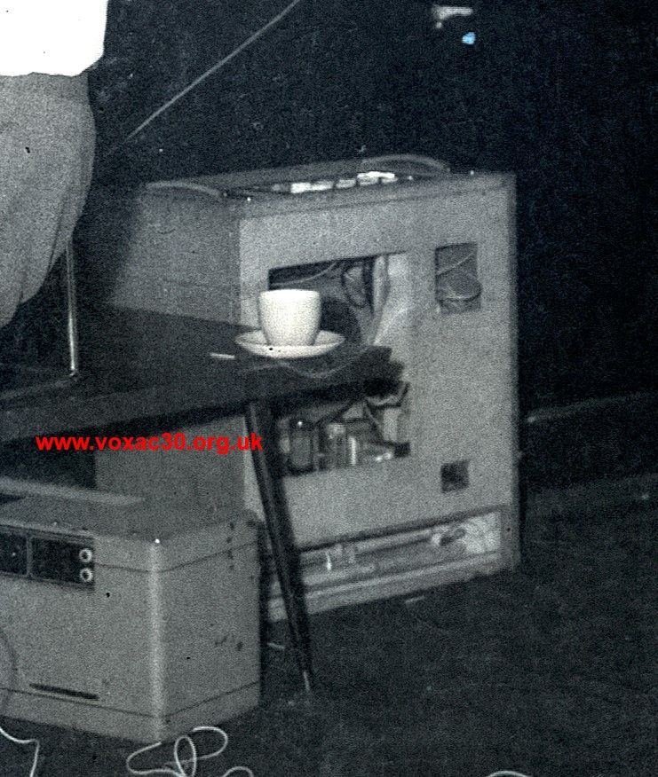
One of the band's Super Twin amplifier sections front down, and the Bird "Golden Eagle".
"Vintage Guitar Magazine" has some useful photos of a surviving "Golden Eagle".
6th September
Below, details of a first generation chrome AC30 stand from a set of negatives of the band "The Black Sheep" rehearsing in a church hall mid to late 1964. The band (two guitarists, a bassist, drummer and keyboard player) are pictured with: two beige AC30 Super Twins; an early chrome stand; an AC30 Twin in black; a reed organ; Vox Continental with sloping top; a Fenton Weill Auditorum 30; a Selmer Bassmaster and Goliath cabinet; a Bird 30 Reverb amplifier; Vortexion PA amplifier to drive a pair of Vox LS40 speakers; Reslo stands and mics; and a fairly rudimentary drum kit. Whether all these things were theirs is unknown.
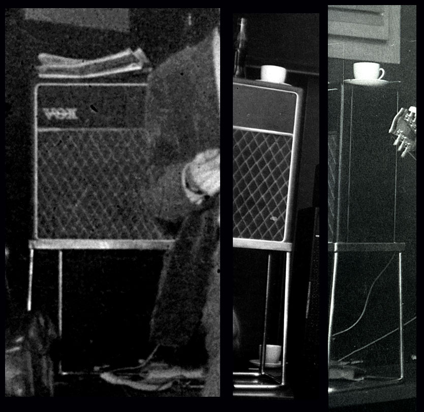
Details of the early AC30 stand belonging to "The Black Sheep", mid to later 1964.
5th September
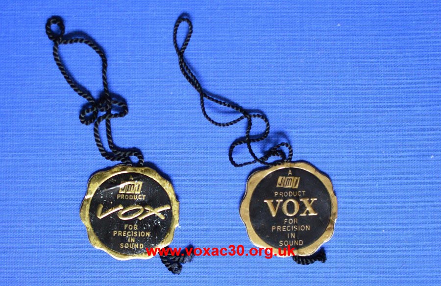
Three types of JMI hang tag. These were normally tied to guitars, accessories, and amplifiers before packing. The two in the first picture are most common: "VOX" in cursive into 1964; "VOX" in block capitals from late 1964 through to 1968.
The example on its own in the second picture is scarcer, encountered so far only on one JMI amp from 1966, and may have been devised principally for exports to the USA. The form of "VOX" is the same as that on the tag devised by Thomas (third picture, below).
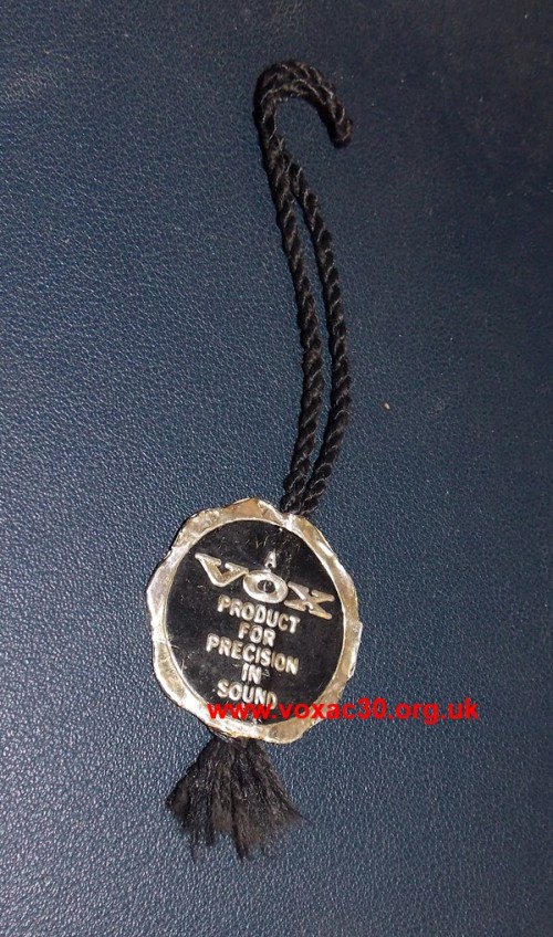
Thanks to Heinz for the picture.
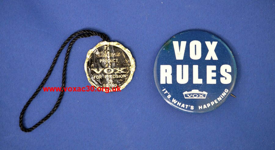
4th September
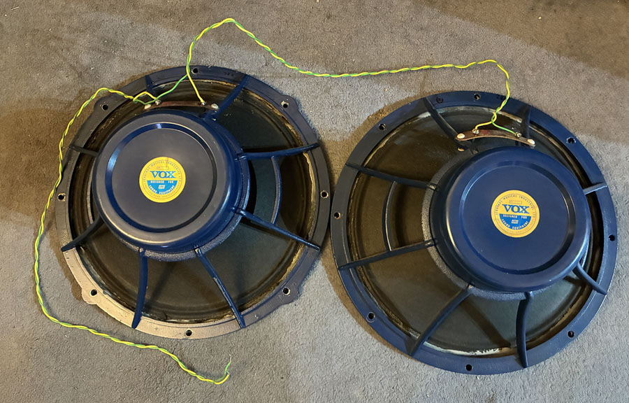
The speakers of AC30X serial number 574, on the left a Celestion T900 from January/February 1964, on the right a T1074 from mid '64. The two are wired in series. As the T900 is normally 4 ohms and the T1074 15 ohms, a total series impedance of 19/20 ohms is in view. The speakers were connected into the 8 ohm tap on the terminal block. Was the T1074 mis-stamped, being in actual fact a 4 ohm T900? If not, power will not only have been unevenly distributed between the two, but the output of the amplifier seriously curtailed by the load on the output transformer.
3rd September
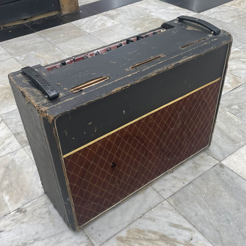
Seen doing the rounds a little while ago, AC30 serial number 7188, its cabinet with sloping edges similar to those on the T60 cabinet mocked up by Mick Bennett, JMI's principal wood craftsman, in 1963.
It certainly seems possible that the AC30 cab was Mick's work, perhaps a trial piece that found its way - for whatever reason - into the production run. The sloping edges, decorative as they are, can hardly have been thought viable either in terms of cost of manufacture or longevity of use though.
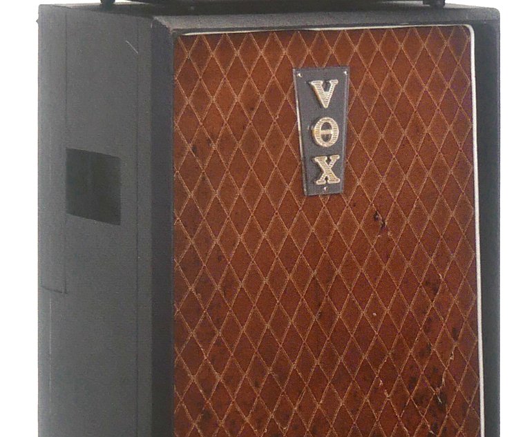
Picture from Jim Elyea's book.
PREVIOUS UPDATE PAGES BY MONTH, 2026
PREVIOUS UPDATE PAGES BY MONTH, 2025
PREVIOUS UPDATE PAGES BY MONTH, 2024
UPDATES 2023
UPDATES 2022
UPDATES 2021
UPDATES 2020